
Temperature Controlled NICD Charger IC LM311
This temperature-controlled constant current battery charger circuit is a sophisticated solution for maintaining the health and longevity of rechargeable batteries. The core principle revolves around monitoring the temperature of the cells during charging, ensuring they are not subjected to overcharging conditions that could lead to damage. The use of a transformer and bridge rectifier enables the conversion of AC voltage to a stable DC output, which is essential for charging operations.
The 7812 voltage regulator plays a crucial role in stabilizing the voltage supplied to the comparator and logic gates, ensuring consistent performance of the control circuitry. The R-S flip-flop configuration using the 4011 NAND gates allows for a simple yet effective method of controlling the charging state based on the input from the start switch and the temperature sensor.
In terms of safety features, the circuit is designed to prevent charging if the battery temperature exceeds a predefined threshold. This feature is critical in avoiding potential hazards associated with overheating batteries. The use of a differential temperature sensor enhances the circuit's ability to adapt to varying environmental conditions, ensuring that it only responds to significant changes in battery temperature, thus optimizing the charging process.
The 7805 voltage regulator's role as a constant current regulator is vital, as it ensures that the charging current remains within safe limits for different types of batteries. The adjustable trickle charge current, set by the 500-ohm resistor, provides a gentle finish to the charging process, allowing the batteries to reach full capacity without stress.
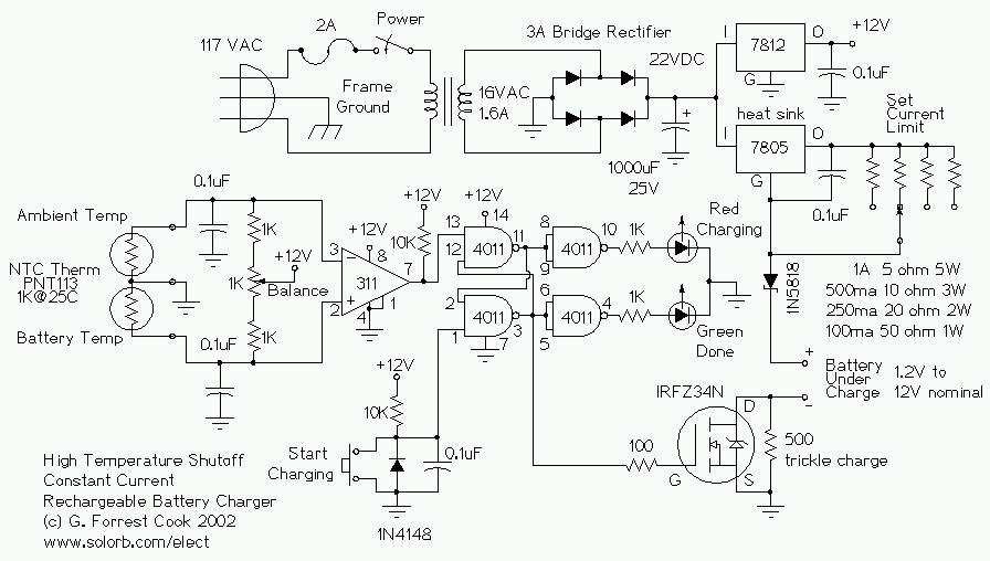
Overall, this circuit exemplifies a well-thought-out design that balances efficiency, safety, and adaptability, making it suitable for various rechargeable battery technologies. The careful selection of components and the thoughtful integration of temperature monitoring ensure that batteries are charged optimally, thereby extending their operational life and reliability.This circuit is for a temperature controlled constant current battery charger. It works with NICD, NIMH, and other rechargeable cells. The circuit works on the principle that most rechargeable batteries show an increase in temperature when the cells becomes fully charged. Overcharging is one of the main causes of short cell life, hot cells pop the ir internal seals and vent out electrolyte. As cells dry out, they lose capacity. The transformer, bridge rectifier, and 1000uF capacitor provide around 22 Volts of DC power to run the rest of the circuit. The 7812 regulator drops this to 12V to run the 311 comparator and 4011 nand gates. The start switch is pressed to start the charging cycle. This causes the two 4011 nand gates, which are wired as an r-s flip-flop, to go into the charging mode.
The Red LED is lit, and the VMOS FET current switch is turned on. Charging current runs though the battery pack. If the battery starts out warmer than the reference temperature, the circuit will not switch into charging mode. Let the pack cool down. When the battery pack reaches a full state of charge, the differential temperature sensor causes the flip-flop to switch off, turning off the VMOS current switch, and lighting the Green LED.
The 7805 voltage regulator is wired as a constant current regulator. This provides a safe maximum charge current for a number of different cell types. The 500 ohm resistor across the VMOS FET sets the trickle charge current which flows through the battery pack after the bulk charging is finished. The differential temperature sensor circuit works by presenting two voltages to the input of the 311 comparator.
The comparator output switches on or off depending on which input is at a higher voltage than the other. As the thermistors warm up, their resistance drops, lowering the associated comparator input. Since there are two sensors, the room temperature can vary and the circuit will only react to the difference in temperature between the sensors.
🔗 External reference
Related Circuits
A DS18S20-based serial port temperature sensor has been developed for connection to the USB port of an Asus WL-500gp v2. The temperature sensor functions correctly when directly connected to a PC's serial port; however, issues arise when attempting to...

A simple battery charger designed for Nickel Metal Hydride batteries that require current-regulated charging. The charger delivers a charging current of 140 mA for efficient battery charging. The power supply section includes a 0-18 volt AC 1 Ampere step-down...

A mobile-controlled robot is a mobile device that offers extensive wireless control capabilities to the robot, as long as the cell phone remains within signal range. The mobile-controlled robot operates through a wireless communication interface, typically utilizing Bluetooth or Wi-Fi...
The schematic consists of four hardware blocks: 1) The wall transformer 2) The charging circuit 3) The control unit 4) The output stage. The circuit schematic is structured around four essential hardware blocks that facilitate the overall functionality of the...
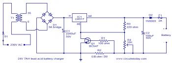
To set up the charging voltage, power on the charger and connect a voltmeter across the output terminals. Adjust R4 until the voltmeter reads 28V. The charger is now ready for battery connection. The charging circuit described involves a voltage...
A company has developed an intelligent temperature monitoring system using the ATMET 89C51 microcontroller. This system automatically records temperature data for a three-phase power supply, including high temperature and other relevant data, functioning as a black box. The ATMET...