
Sensor Alarm using thyristor circuit

The described circuit functions as a simple timing alarm system, utilizing a sensor switch (SW2) to initiate the activation of an LED (D3) and an alarm. The operation begins when SW2 is pressed, which closes the circuit and allows current to flow. The LED serves as a visual indicator, while the alarm provides an audible signal, enhancing the alertness of the system.
The timing mechanism is established through the combination of resistor R3 and capacitor C1, forming an RC timing circuit. The time constant of this circuit, defined as τ (tau), is calculated using the formula τ = R3 * C1. This time constant determines how long the LED and alarm remain active after the switch is pressed. The discharge of capacitor C1 through resistor R3 controls the timing interval, allowing for adjustable delay periods by varying the values of R3 and C1.
In addition to the timing function, the circuit incorporates a C106M Thyristor, which is a type of semiconductor device that can control power. The Thyristor is used to switch the load (in this case, the alarm) on and off. Upon pressing SW2, a small gate current is applied to the Thyristor, allowing it to conduct and energize the load. Once triggered, the Thyristor remains in the conducting state until the current through it drops below a certain threshold, which is influenced by the timing circuit.
For further understanding of the C106M Thyristor's specifications and operational characteristics, referring to its data sheet is recommended. This document provides essential information regarding voltage ratings, current handling capabilities, and other critical parameters necessary for proper integration into the circuit.When you press sensor switch SW2, the LED D3 and the alarm switches ON for a while. The timing of the circuit is dependent upon R3 and C1. You can get all the details of the RC circuit from the links given above. You can see on the schematic that the circuit is based on C106M Thyristor. Download data sheet of C106M Thyristor 🔗 External reference
Related Circuits
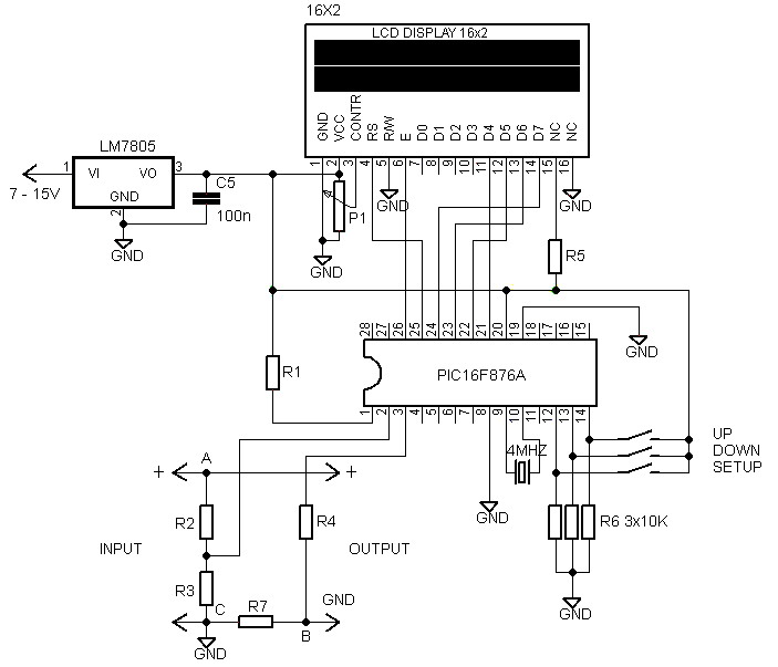
A voltmeter and ammeter using a PIC microcontroller can measure voltage and current simultaneously. This setup employs a PIC16F876A as the data processor for voltage and current measurements. An LCD display (16x2) is utilized to present the measured voltage...
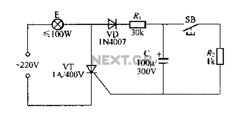
Figure 57 illustrates a simple delay lamp circuit that connects to lamp E using a two-wire connection. This design allows for the security bars to be installed directly, enabling replacement with a standard wall switch without altering the existing...
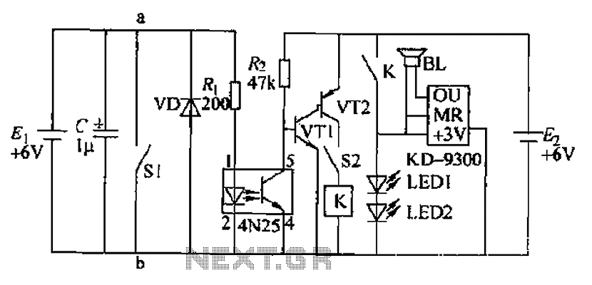
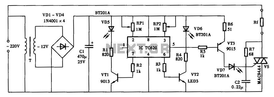
Due to the fast pace of modern life, intense competition, and widespread insomnia, which poses health risks, this section presents a feasible and effective method for controlling photoelectric hypnotic music to alleviate insomnia and facilitate sleep. The principle circuit...
This circuit illustrates a remote control system utilizing a radio telephone circuit diagram. Features include the ability to switch appliances from any distance, overcoming various limitations. The remote control circuit employs radio frequency (RF) technology to facilitate wireless communication between...
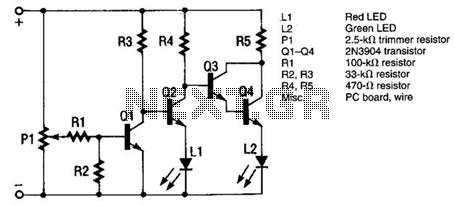
The monitor functions as a basic voltage comparator, utilizing a car battery as its power source. The input voltage to the comparator is adjusted using potentiometer PI. This adjustment ensures that the green LED L2 illuminates when the alternator...
The thermostat can be set, and it specifies the lower limit of the circuit diagram. The thermostat in the circuit is a critical component used to regulate temperature by controlling the heating or cooling system. It operates by comparing the...