
Temperature Controler switch

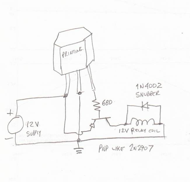
Higher power transistors can be substituted for bigger fans, or a relay, IGBT, MOSFET, etc., can be used to control higher loads (and higher voltages).
The setpoint is adjusted with the potentiometer, and a LM3914 LED driver can be employed to create a temperature setpoint indicator (requiring careful calibration and the use of Excel to calculate slope and intercept).
Many modifications can be made, but the circuit works very well in its basic form.
The comparator can distinguish 10µV differences, equating to approximately 0.01°C differences (carefully adjusting the potentiometer can allow detection of body heat from 1/2 cm from the sensor or ambient heat, causing the fan to turn on and off continuously).
Temperature control is possible up to 140°C (150°C maximum diode temperature), but linearity is not ensured.
Possible applications include heatsink cooling, emergency computer cooling (though a linear device may be preferable to an on-off configuration), and metal cooling during drilling, among others.
This circuit can also be adapted for heating applications by reversing the comparator inputs and substituting the fan with a relay that controls the heater.
The circuit employs a basic design that leverages the temperature-dependent characteristics of a diode to provide a reliable and responsive control mechanism for fans or heating elements. The use of a Zener diode as a reference voltage source ensures precision in temperature detection, while the LM158/258/358 operational amplifier functions as a comparator to switch the load based on the setpoint. Adjustability is facilitated through a potentiometer, allowing for fine-tuning of the desired operating temperature. The circuit's versatility enables it to be applied in various thermal management scenarios, making it a practical solution for both cooling and heating applications.This circuit controls a load (in this case a dc brushless fan) based on a temperature compared with a setpoint. THe transduced is a diode in the forward polarization regime. In fact when forward biased, the forward voltage drop accross a diode has a temperature dependance, in particular has a negative linear(ish) slope.
This because of the boltzmann distribuition, causing electrons to pass to the conduction band thermically, lowering the voltage drop accross the diode. Anyway this circuit comparates a precise voltage reference (zener) with the forward voltage drop of the diode forward biased with 11mA of current.
The comparator is simply a LM158/258/358 working in open-loop mode, the inverting input is connected to the diode sensor, and the noninverting to the reference voltage. Se when the temperature rises above the setpoint, the forward voltage drops under the voltage reference and the comparator output is vccturning on the transistor and so the fan.
Higher power transistor can be substituted for bigger fans, or you can substitute a relay, IGBT, mosfet etc to control higher loads (and higher voltages). The setpoint is adjusted with the potentiometer, and you can use a LM3914 led driver to make a temperature setpoint indicator (needs careful calibrations and the use of excel to calculate slope and intercept).
Many modifications can be done, but the circuit works very well in its basic form. THe comparator can distinguish 10uV differences so approx 0.01°C differences (carefully adjusting the potentiometer can allow to feel body heat from 1/2 cm from the sensor, or feel ambient heat, making to turn the fan on and off continuosly) You can control temperatures up to 140°C (150 max diode temperature), but linearity is not ensured Possible uses? Heatsink cooling, computer emergency cooling (but i thint that a linear device would be better than a on-off) metal cooling when drilling etc...
Ah! One note: you can even heat with this circuit but you need the reverse comparator inputs and substitute the fan with a relay controlling the heater. 🔗 External reference
Related Circuits
Each audio/video output can be switched to any of the eight inputs separately. One module drives one audio/video output and has a 34-pin connector to plug into the system interface. Video operational amplifiers (OPAs) can be used on the...

Today's electronic designs focus on optimizing efficiency to minimize unnecessary power dissipation, aiming to maximize battery life in portable applications and ensure that devices operate as cool as possible. One of the challenges facing designers of synchronous buck PWM...
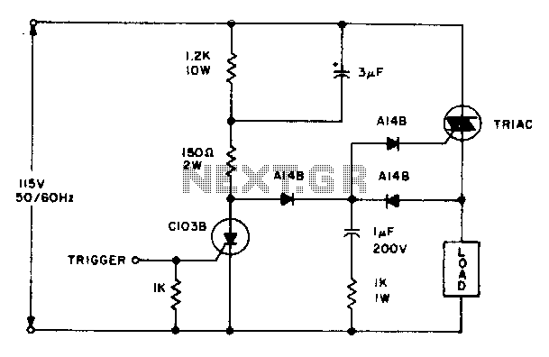
The triac will be activated at the beginning of the positive half cycle due to the current flowing through the 3 µF capacitor, provided that the C103 SCR is in the off state. The load voltage subsequently charges the...
An ultra-sensitive gauss meter circuit schematic serves as a simple indicator with no measurement, scaling, or accuracy. It consists of a Hall effect device or integrated circuit on a board with power supply inputs, minimal signal conditioning comprising approximately...
This heatsink temperature monitor circuit uses three LEDs to signal when the temperature exceeds two boundary levels. When the heatsink temperature is below 50-60°C (122-140°F), the green LED lights up. The yellow LED indicates that the temperature is between...
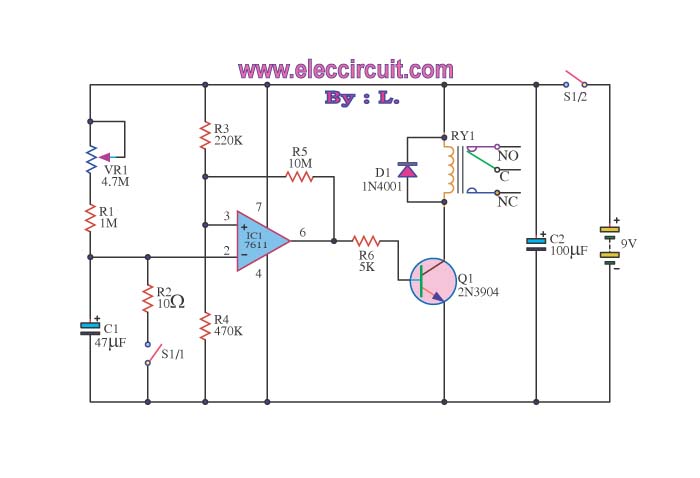
When switch S1/2 is activated, it powers the circuit C1, which utilizes the UA741 operational amplifier for voltage comparison. Pin 3 serves as the non-inverting input, while pin 2 is the inverting input. The voltage at pin 3 is...