
simple gauss detection switch
The ultra-sensitive gauss meter circuit is designed to detect magnetic fields with high sensitivity, utilizing a Hall effect sensor, which is a transducer that varies its output voltage in response to a magnetic field. The circuit typically includes a power supply section that provides the necessary voltage to the Hall sensor and other components. The Hall effect sensor generates a small voltage output, approximately 1.3mV per Gauss, which necessitates signal conditioning to amplify and filter this signal for practical use.
Signal conditioning may involve operational amplifiers to increase the output voltage, along with resistors and capacitors to form filters that eliminate noise and stabilize the output. This ensures that the small variations in voltage can be accurately interpreted by subsequent circuitry. A relay may be included in the design to act as a switch that activates or deactivates a load based on the detected magnetic field strength.
The choice of the Hall effect sensor integrated circuit is crucial, as its characteristics will determine the overall sensitivity and performance of the circuit. The circuit may be optimized by experimenting with the placement of the sensor within ferrite rings, which can enhance the magnetic field's strength at the sensor's location, thereby improving the sensitivity of the measurement.
While magneto-resistive and magneto-inductive sensors are alternatives used in applications like compasses, they are often more complex and less accessible than Hall effect sensors. The simplicity of the Hall effect sensor circuit makes it an attractive option for various applications, provided that the limitations of the sensor are understood and addressed. Overall, this circuit can serve as a foundational design for those seeking to create a sensitive magnetic field detection system with minimal complexity.An ultra sensitive gauss meter circuit/schematic anywhere that constitutes a simple indicator No measurement. No scaling. No accuracy. Just hall device/ic on a board with power supply inputs, a bit of signal conditioning of maybe a dozen more parts, and a little relay.
If you look at the linear hall effect sensor it has an output of 1. 3mV per Gauss. That might be the limitation of hall effect sensors in general which might be where all your problems are coming from. It`s got me wondering why you never see hall effect sensors in things like compasses. You always see some kind of magneto-resistive or magneto-inductive sensor for those kinds of things, but those are neither straightforward to work with, nor easily available. Is it possible to implement so simple a circuit Or are these merely rough application examples Sensitivity would only depend on the IC that is inserted, no I`m in the process of testing that last one and it may work for me.
But I`ve asked a few questions about it here and elsewhere and don`t seem to be making any headway. The simpler the better. I just want an ultra sensitive switch circuit. I`m experimenting with placement of the sensor chip in various ferrite rings for better sensitivity. Here`s one example. 🔗 External reference
Related Circuits
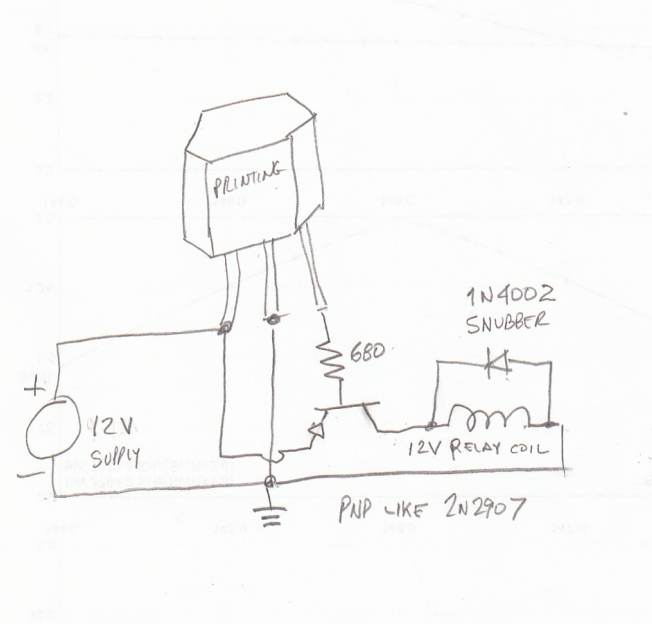
This page outlines the hardware and software design of a printer power switch that is controlled via USB from a Linksys NSLU2, also referred to as Slug. Although primarily designed for printer control, the unit can manage any device...
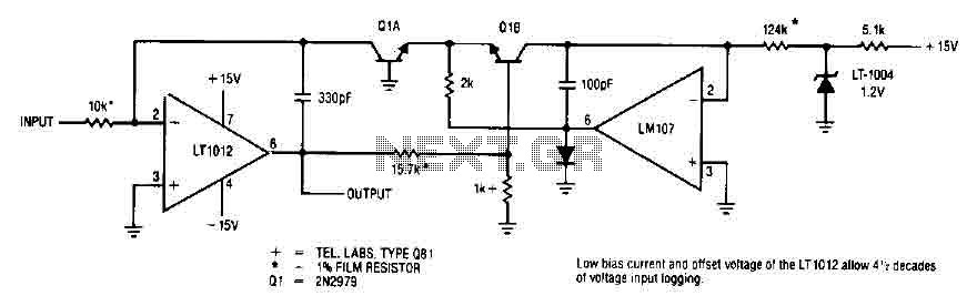
This simple logarithmic amplifier circuit uses the LT1012, which has a low bias current that allows for 4.5 decades of voltage input logging. Additionally, transistors that can be used in this circuit include the 2N2979. The logarithmic amplifier circuit designed...
This project schematic illustrates an LM741 dark sensor relay switch circuit. The circuit is designed to activate a relay switch in the absence of light on the surface of a Light Dependent Resistor (LDR). The LM741 operational amplifier is utilized...
The receiver circuit in Figure 1 activates an audio alarm when the transmitter (Figure 2) moves beyond a specified perimeter. The transmitter functions as a voltage-controlled oscillator, operating at approximately 915 MHz within the unlicensed ISM (industrial/scientific/medical) band. It...
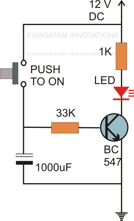
Without the specified delay, the circuit could malfunction or even sustain damage. A capacitor, which is a crucial component of the circuit, is positioned at the other end of the base resistor rather than directly connected to the base...
This light-sensitive automatic light switch circuit is designed to be connected to the main 220V supply. The circuit will activate a 220V lamp during nighttime. The light-sensitive automatic light switch circuit operates by utilizing a light-dependent resistor (LDR) to detect...