
Tesla HV Coil
Warning: Undefined array key "extension" in /var/www/html/nextgr/view-circuit.php on line 477
Deprecated: strtolower(): Passing null to parameter #1 ($string) of type string is deprecated in /var/www/html/nextgr/view-circuit.php on line 477

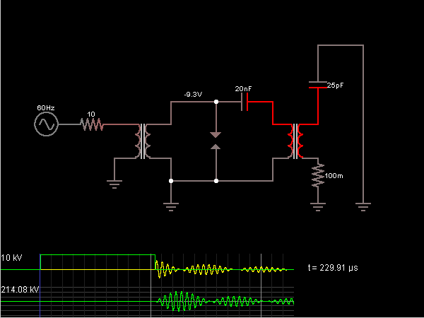
The operation of a Tesla coil through a spark gap involves the generation of high-voltage, high-frequency oscillations, which are critical for establishing standing waves within the coil. The fundamental frequency at which the coil resonates is determined by its physical dimensions, specifically the length of the wire used. For optimal performance, the length of the secondary coil should correspond to a quarter wavelength of the excitation frequency. This relationship is essential for maximizing the efficiency of energy transfer and achieving the desired electrical characteristics.
In Tesla coil design, the aspect ratio of the coil—whether short and fat or tall and skinny—affects the coil's performance. Short-fat coils, which have a larger diameter, tend to store more energy in the inter-turn capacitance, leading to higher voltage differences between adjacent turns. This configuration is advantageous for maximizing power transfer between the primary and secondary coils, making it suitable for applications that require efficient energy transfer.
Conversely, tall-skinny coils are designed for applications that involve the transmission of power over distances. They are more effective in creating an electric field that can propagate energy through the air, which is particularly useful in demonstrations of wireless power transmission. In small Tesla power plants, such as the one described, the coil can draw minimal power from the mains while still being capable of lighting multiple fluorescent bulbs at a distance. This illustrates the effectiveness of the Tesla coil design in harnessing and transmitting electrical energy in a wireless format.
The adjustment of the spark gap is a critical factor in controlling the output of the Tesla coil. By varying the gap, the operator can manipulate the frequency and amplitude of the oscillations, thus affecting the overall performance and range of the coil. As the gap is opened, the energy output increases, allowing for greater distances of wireless power transmission. This principle underlies many practical applications of Tesla coils in both experimental and educational settings, where the demonstration of electrical phenomena is desired.Is it (when operated through a spark gap) allways a quarter wave, or a half wave or multiple of a whole wave so that there are 2* n maximums that are achieved. Can someone point out to sources that are related to creating standing waves and the resonance frequency of the coils.
On the secondary is only a load put on. What I wanted to say was that if it is a Tesla coil configuration and you want the points of max excitations on the ends of the coil(tesla coil) the excitation f and the speed of the propagation of impuses c determines the lenght of the coil. The no of turns is not important, the lenght is. The impulse travels from the beginning of the coil - wire and back. So the higher the f the shorter a coil. A Tesla secondary should use a length of wire that is equal to a quarter-wavelength of the excitation frequency.
The number of turns comes into play when deciding whether to use a short-fat form, or a tall-skinny form. Substantial energy can be stored in inter-turn capacitance. In a short fat coil, there is more voltage difference between adjacent windings than there is in a tall skinny coil.
Short fat coils work better for maximum power transfer between primary and secondary. Tall skinny coils work better for transmitting power across space, as in this small Tesla power plant. This power plant is drawing only a few Watts (35 or so here) from the mains, and yet it will light up as many fluorescent bulbs as you can hold near it.
Turn up the power (by opening the gap, bottom right, now nearly completely closed) and the range increases proportionally. 🔗 External reference
Related Circuits
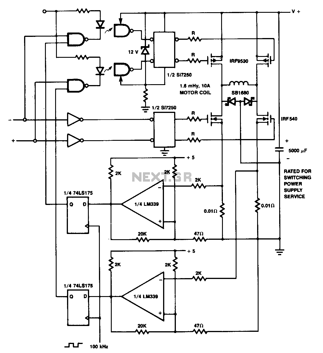
The p-channel devices are deactivated by current sensors when the coil current reaches 10 A. The operation resembles that of a switching-type power supply. Additionally, Schottky diodes and resistors are utilized for spike protection. In this circuit, p-channel MOSFETs serve...
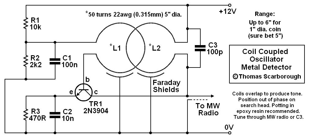
A coil-coupled operation metal detector constructed from commonly available components, utilizing a standard medium receiver as the detection unit. The coil-coupled operation metal detector functions by employing a transmitter coil and a receiver coil that are magnetically coupled. The transmitter...
This is the Tesla Coil circuit diagram with a detailed explanation of its working principles. The electronic circuit simulator aids in designing the Tesla Coil circuit and simulating it online for better understanding. The Tesla Coil is a resonant transformer...
This circuit is designed to demonstrate high frequency and high voltage, capable of producing up to approximately 30 kV, depending on the transformer utilized. It is an economical and straightforward project, primarily using a standard TV flyback transformer. The...
Tesla's free-energy receiver was patented in 1901 as An Apparatus for the Utilization of Radiant Energy. The patent refers to "the Sun, as well as other sources of radiant energy, like cosmic rays." That the device works at night...

The component in question is complex, seemingly consisting of three capacitors: two virtual capacitors and one physical capacitor. Initial observations indicate that the voltage is increasing, and the LED brightness is also improving. Battery B1 appears to be discharging...