
Captret and Tesla switch
Warning: Undefined array key "extension" in /var/www/html/nextgr/view-circuit.php on line 468
Deprecated: strtolower(): Passing null to parameter #1 ($string) of type string is deprecated in /var/www/html/nextgr/view-circuit.php on line 468

The circuit design revolves around a novel component referred to as the "captret," which operates using a combination of physical and virtual capacitors. The primary physical capacitor, designated as C1, is central to the energy storage and transfer process. The virtual capacitors, VC1 and VC2, are created through the circuit configuration, allowing for dynamic voltage management between points A, B, and C.
When switch S1 is closed, a charging cycle initiates where B1 supplies energy to C1. The voltage across VC1 (between A and C) and VC2 (between C and B) is established, with VC1 achieving approximately 75% of C1's voltage and VC2 reaching about 25%. This unique arrangement allows for the simultaneous storage and redistribution of energy within the circuit.
The operation of the flip-flop mechanism is critical for efficient energy transfer. By alternating the states of switches S3 and S5, the circuit can transfer charge between VC1 and VC2 with minimal energy loss. The blinking of LED D2 during this process indicates successful energy transfer and utilization. The low current draw of less than 2mA from batteries B1 and B2 demonstrates the circuit's efficiency, as it is capable of lighting the LEDs without significant power consumption.
The experimental results challenge traditional capacitor behavior, suggesting that the energy dynamics within the captret allow for a more efficient transfer of charge than typically observed. This phenomenon may indicate the presence of an excess energy source, potentially leading to over-unity (OU) conditions in the circuit, as inferred from the behavior of VC1 and VC2.
The graphical representations accompanying the circuit diagrams provide insights into the voltage interactions and the overall performance of the captret. The various configurations and their corresponding graphs illustrate the operational characteristics and potential advantages of this innovative circuit design, paving the way for further exploration and application in energy-efficient electronic systems.It is a complex component to say the least. It is as if it is composed of 3 caps being 2 virtual plus the known cap itself. On my first graph I am showing the log of the progess of the running and sucessfull version shown on my youtube videos. Voltage is still going up andLED is a little bit more bright now. I also noticed that battery B1 is drainning more than charging although I dont have its initial starting voltage.
I would vconclude on very little data on B1 that it is going down with time. Battery B2 on the contrary is indeed charging with time which explains the LED getting brighter too. I think that if B1 continues going down I can swap the two batteries and let the process continue. Time will tell. So far I call this version of the captret a total sucess. On the second picture (Flip/Flop on virtual caps) I noticed that the captret works as if it has two extra virtual caps between the two poles (points A and B). I named them VC1 (points A and C) and VC2 (points C and B). Starting with an empty cap when closing switch S1 battery B1 will charge cap C1. At the same time the voltage on the points A and C (virtual cap VC1) will also have a certain voltage of about 3/4 of C1 (A positive and C negative).
Virtual cap VC2 will be also about 1/4 of C1 voltage (C positive and B negative). Upon opening S3 and closing S5, LED D2 will blink and VC2 will go to zero while VC1 will be the same voltage of C1 (after losses on C1 voltage). So C1 will be a little bit less than when we started and VC1 will be that same voltage of C1. That`s why I called this diagram FLIP-FLOP, since one can switch S3 and S5 alternatively and have about 90% or more of the virtual caps VC1 and VC2 simply transfering to themselfs their charge with little loss while doing work.
One can also, during this FLIP-FLOP process, use that energy transfer and light LEDs as I am showing. I also built a simple circuit to prove that proccess and indeed it works. I think the laws of transfer of charge in capacitors DOES NOT work here since my experimental analysis has demonstrated to only have a small loss of power instead of the theoretical known 50%.
THIS BY ITSELF IS PHENOMENAL. When the virtual charges on VC1 and VC2 are gone we still have about 50% or more of the initial voltage on C1 left to be used one more time by switching S7 and having LED D3 to light. The current on D1 and D2 is in the range of less than 2ma but incredible enough it still lights those LEDs to a shinning blink.
This low amperage and the fact the the "charges" are moving around VC1 and VC2 and not behaving as the conventional transfer of charges of capacitors (which should loose always at least 50% at every instance) makes me believe that this is not a conventional charge as is thought. On the last picture we have a series of graphs and circuit digrams showing the behavior of the captret when voltage is applied and when the power stored on cap C1 is used.
Take note that we have 4 diffferent configurations and their corresponding graphs beneat them. Graph G2 (of more value) is expanded to the bottom right so that one can see the interaction of voltages among all the virtual caps VC1 and VC2 and the main cap C1. It is strange all by itself that the relative positve and negative references of potential among all the virtual caps is logical and at the same time illogical since physically we would understand or infer that point C is common to virtual caps VC1 and VC2 and YET have different potential in relation to A and B while easily transfering charges around without much loss.
I could not even come up with a good theoretical diagram that could "represent" a captret. I am forced to infer that, if OU is present on my running captret circuit (shown on the videos), it must be because of this "extra" charge present on VC1 and VC2 and as presented on the graph G2 it is 🔗 External reference
Related Circuits
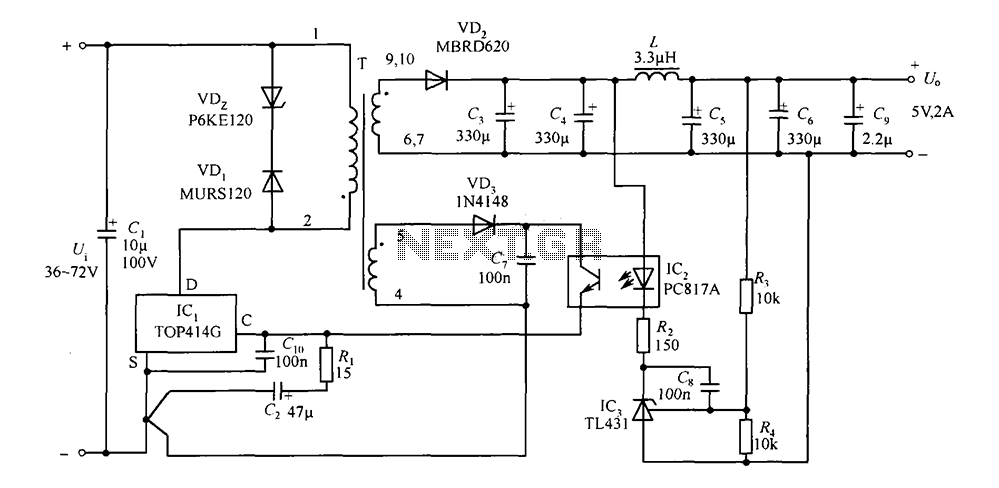
The circuit consists of a 5V TOP414G isolated switching power supply with a 2A output. C1 serves as the input filter capacitor. The circuit includes a voltage clamp protection mechanism composed of VD1. The control terminal is connected to...
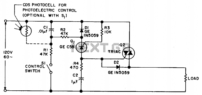
Synchronous switching activates only when the AC supply voltage crosses zero and deactivates only when the current reaches zero. This circuit responds to either a mechanical switch or a variable resistance, such as a cadmium-sulfide photocell. It minimizes disturbances...
Under the loading condition of the resistance, the output voltage (Uo) variable range is from 30V to 36V, with a maximum output current (Imax) of 2A. When the input voltage (U2) changes from 15V to 21V, the voltage regulation...
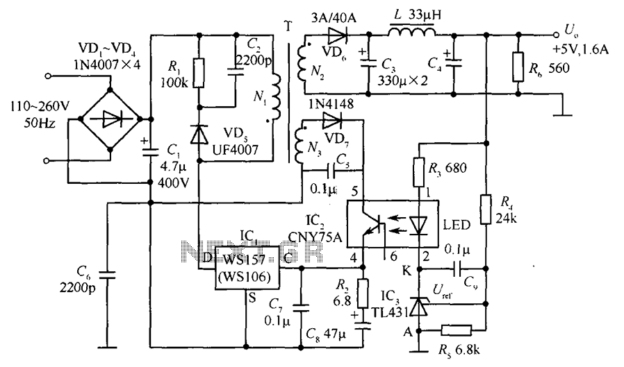
The circuit incorporates an optical coupler (CNY75A) and an adjustable precision shunt regulator (TL431). It includes current limiting resistors R3, R4, and R5 for the sampling resistor. As the output voltage (Uo) varies, the voltage across the sampling resistor...
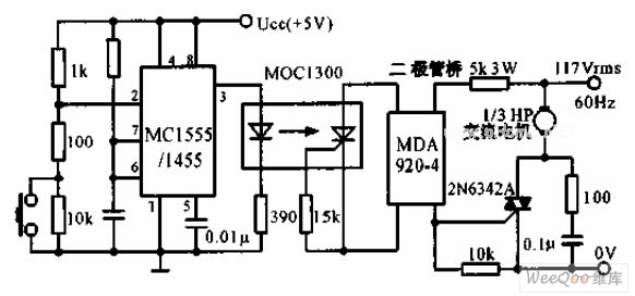
The switch shut-off time delay circuit consists of a timer, optocouplers, a bridge SCR, and an SCR AC switch. When the control button is released, it allows the motor or other AC power to remain active for one hour....
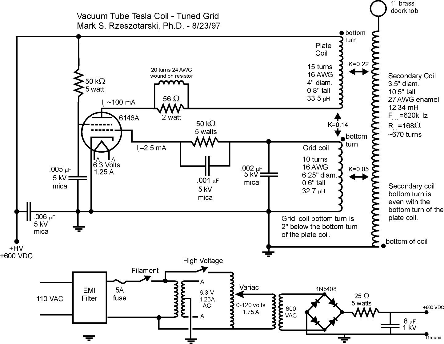
Vacuum tube Tesla coils operate in a continuous wave mode, providing constant energy to the Tesla coil secondary. Consequently, the output is mainly determined by the power capacity of the vacuum tube. The spark discharge and operation of these...