
Test Bench Power Supply Schematic
The power supply circuit in question is designed to convert the 120 volts AC from the mains into a usable DC voltage for various electronic applications. The circuit typically includes a transformer, rectifier, filter, and voltage regulator components.
1. **Transformer**: The transformer steps down the 120 volts AC to a lower voltage suitable for the intended application. It also provides electrical isolation from the mains, enhancing safety.
2. **Rectifier**: Following the transformer, a rectifier circuit is employed, commonly using diodes to convert the AC voltage to pulsating DC. A full-wave bridge rectifier configuration is often utilized for better efficiency and smoother output.
3. **Filter**: The output from the rectifier is then passed through a filter, usually consisting of capacitors, to smooth out the pulsating DC into a more constant voltage. This stage is crucial for reducing ripple voltage, ensuring that the output is stable and suitable for powering sensitive electronic devices.
4. **Voltage Regulator**: Finally, a voltage regulator may be included to maintain a constant output voltage despite variations in input voltage or load conditions. This component is essential for applications where precise voltage levels are critical.
Safety precautions must be observed when working with high voltages. Proper insulation, fuses, and circuit protection devices should be implemented to prevent electrical hazards. Additionally, all components should be rated for the expected voltage and current levels to ensure reliable operation and prevent component failure.
This power supply circuit is commonly used in various applications, including powering microcontrollers, sensors, or other electronic devices that require a stable DC voltage.This power supply circuit uses 120 volts household mains and should only be attempted by someone that has the knowledge and skills to safely construct such a project. Otherwise personal injury and or property damage could result. 🔗 External reference
Related Circuits
Nearly all modern computers are equipped with logic blocks that facilitate the implementation of a USB port. A USB port can deliver over 100 mA of continuous current at 5V to peripherals connected to the bus. Therefore, it serves...
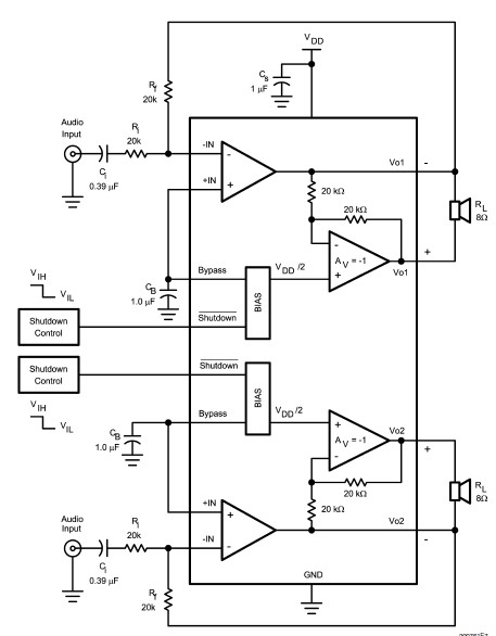
The LM4992 stereo audio power amplifier can be utilized to design a straightforward audio power amplifier project suitable for portable electronic devices. This amplifier circuit is capable of delivering 1 watt of continuous average power per channel to an...
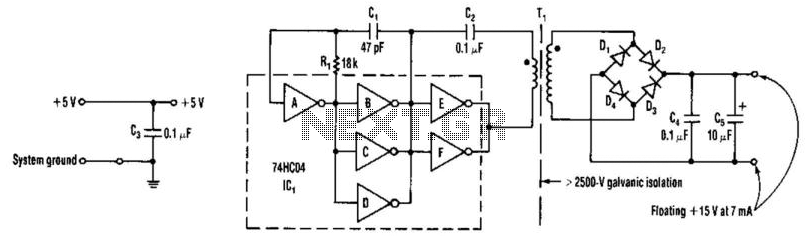
A DC-DC converter utilizes a 74HC04 to drive transformer Tl. Tl is a ferrite-core transformer from Fair-Rite, Inc., with part number 597-5000201, featuring a 7-turn primary winding and a 25-turn secondary winding. Kynar #30 wire wrap wire is employed...

A simple yet reliable car battery tester circuit diagram. This circuit utilizes the popular and easily accessible LM3914 integrated circuit (IC). The LM3914 is straightforward to operate, does not require external voltage regulators due to its built-in voltage regulator,...
The induction coil detects the magnetic field flux during phone calls, amplifies the signal, and triggers the LED. These circuits are designed for the phone to rest on the pickup coil. The electromotive force (emf) from the bell electromagnets...
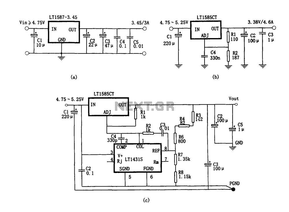
Figure (a) illustrates a microprocessor power supply circuit utilizing the LT1587-3.45. Figure (b) depicts a power supply with an adjustable output voltage constructed using the LT1585. Figure (c) showcases a computer power supply circuit formed with the LT1584 and...