
using call detector circuit schematic
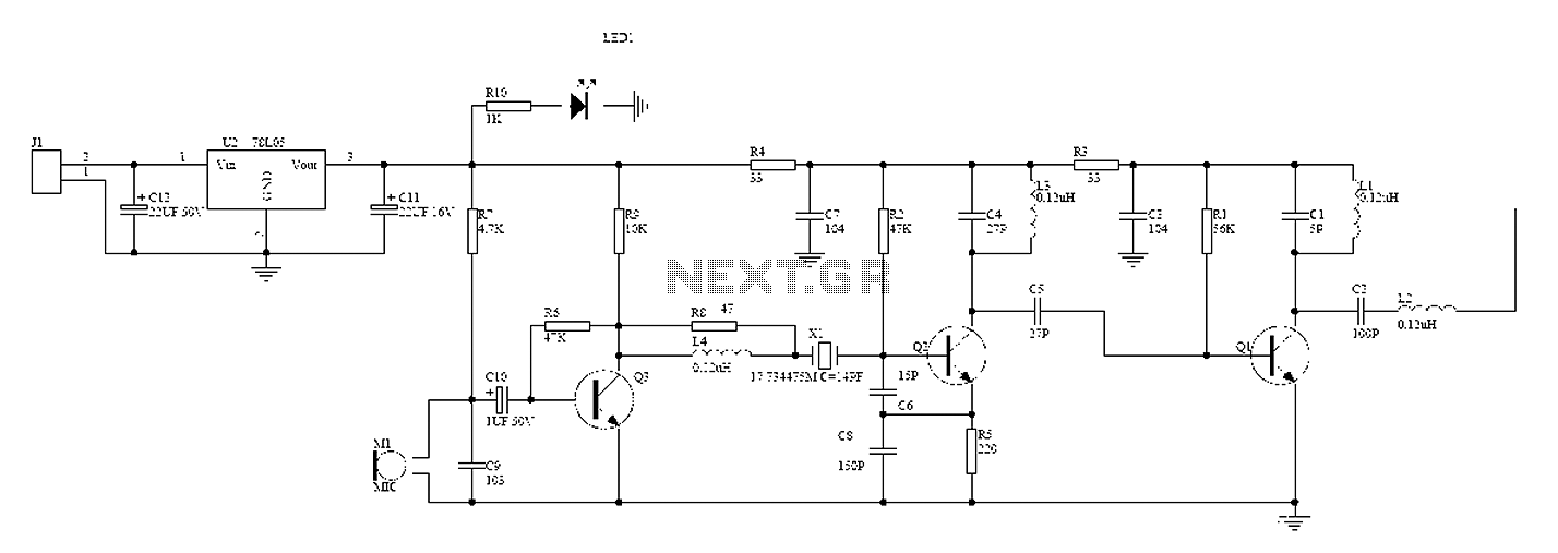
The described circuit employs an induction coil to sense the magnetic field generated by a ringing phone, which activates an LED indicator. The design requires the phone to be placed directly on the pickup coil to ensure effective signal capture. The induction coil's operation is based on the principle of electromagnetic induction, where the changing magnetic field from the phone generates a voltage in the coil, allowing for signal amplification.
The circuit's input stage utilizes a specialized oil that enhances the detection of the radio frequency (RF) signal emitted by the phone, particularly during incoming calls. This signal is crucial for the circuit's functionality, as it indicates the phone is ringing. However, it is important to note that RF circuits can be sensitive to layout and construction; hence, breadboarding can introduce complications such as unwanted oscillations and interference due to the high capacitance between closely spaced contacts.
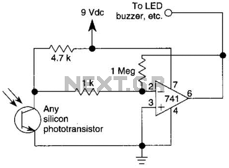
The 7555 timer IC is referenced for its operational voltage range, which is essential for ensuring the circuit functions correctly. The recommendation to test the circuit at 3 volts using two 1.5-volt cells is grounded in the need to provide sufficient power while minimizing the risk of damage to the components. Adjustments to the resistors may be necessary to optimize performance, particularly if the circuit is not responding as expected.
In summary, the circuit design focuses on capturing the electromagnetic signals from a phone to activate an LED, while also addressing common pitfalls in RF circuit construction, particularly on breadboards. Careful consideration of component specifications and circuit layout will enhance the likelihood of successful operation.and I think I understand what`s going on. the induction coil senses the magnetic field flux around when the phone calls, boosts the signal, and pulses the LED. These types of circuits were meant to have the phone sitting on the pickup coil. The emf from the bell electromagnets were picked up. As Nigel said they won`t work with modern phones. The c oil at the input of the circuit is supposed to pickup the radio signal of the cell-phone when it is called and it is transmitting, "I am receiving the ringing". But most RF circuits do not work when made on a breadboard because the tangle of wires are confusing, pickup interference and cause oscillation.
The capacitance between rows of contacts is too high. Also the contacts are intermittent. I am going to venture a guess. If you look at the 7555 data sheet they are pretty clear about " Guaranteed Supply Voltage Range. . . . . . . . . 2V to 18V". What they are saying is that the chip will work with a minimum of 2 volts. Some will work at 1. 5 volts while some may not. Given that, I would use a pair of 1. 5 volt cells and try running at about 3 volts as a test. You may need to change a few values of resistors but I would give 3 volts a try. That assumes you are wired correctly. That would be my first guess anyway. AG has a good point with RF but I would try a higher voltage. 🔗 External reference
Related Circuits
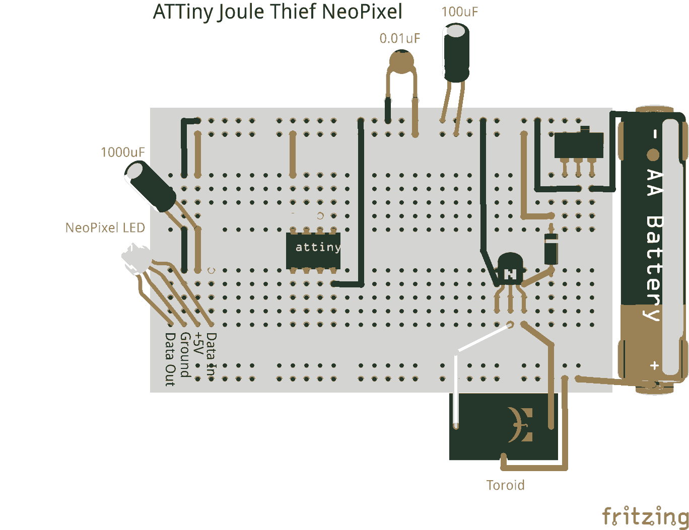
Joule thieves are not limited to illuminating standard LEDs. They can be utilized with an ATtiny microcontroller to power NeoPixel LEDs. Joule thieves are simple and efficient circuits designed to extract and boost low voltage energy from sources such as...
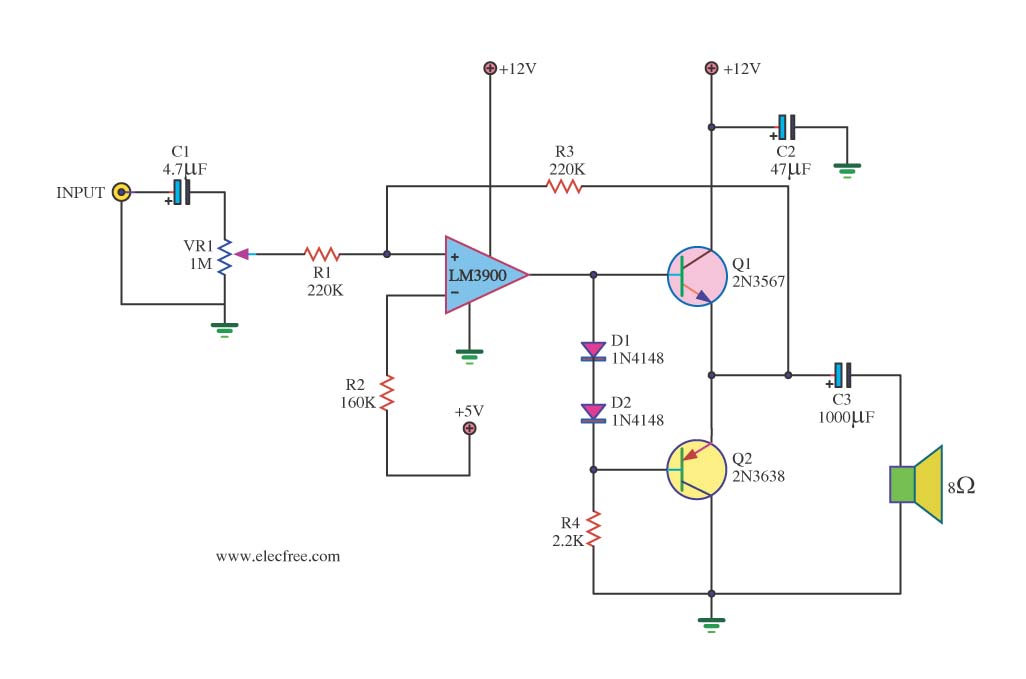
This is a mini-sized power amplifier rated at 2 watts OTL that utilizes the LM380 integrated circuit. It serves as a ready-made circuit for audio applications and communication, requiring minimal external equipment. The capacitor C6 can be selected from...
This circuit represents one of the simplest infrared (IR) receivers that can be constructed. The components are inexpensive, the layout is not critical, and a 9-V battery provides a long operational life. The described IR receiver circuit typically consists of...
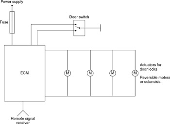
A central door locking system allows all doors, including the boot lid or tailgate, to be locked centrally from the driver's door, typically including the front passenger's door as well. The locking and unlocking actions are performed by an...
The circuit integrates several functions, including a smooth startup for the AC power line, with a one-second delay before connecting to the power supply transformers of the amplifier through relay RL1 and resistor Rx. This delay is designed to...
A wireless hands-free telephone device circuit diagram is presented below. The wireless hands-free telephone device circuit diagram typically comprises several key components that work together to enable hands-free communication. The primary components include a microphone, speaker, Bluetooth module, power supply,...