
usb power socket with indicator
The described circuit serves as a practical solution for powering and recharging USB devices from a vehicle's cigarette lighter socket. The use of the LM317L voltage regulator is essential for achieving the desired output voltage and current, ensuring compatibility with various USB-powered devices. The configuration of resistors R1 and R2 is critical, as they determine the output voltage based on the formula provided in the LM317L datasheet. The stability of the output voltage is enhanced by the inclusion of capacitor C1, which mitigates fluctuations in the input voltage that could affect performance.
Incorporating a red LED indicator allows users to easily ascertain whether the circuit is operational, providing a visual cue that the USB port is active and ready to charge devices. The addition of the zener diode (ZD1) is a vital safety feature, protecting the circuit from potential overvoltage conditions that could damage connected devices.
When assembling the circuit on a general-purpose PCB, attention should be paid to layout considerations, ensuring that the components are placed to minimize interference and maintain a compact design. The enclosure should be designed to allow for adequate ventilation to prevent overheating, especially during prolonged use.
Overall, this USB power socket circuit exemplifies a versatile and efficient method for utilizing existing vehicle power sources to charge and power portable electronic devices, making it a valuable addition to any automotive accessory lineup. Proper implementation and attention to detail during assembly will result in a reliable and functional product.Today, almost all computers contain logic blocks for implementing a USB port. A USB port, in practice, is capable of delivering more than 100 mA of continuous current at 5V to the peripherals that are connected to the bus. So a USB port can be used, without any trouble, for powering 5V DC operated tiny electronic gadgets. Nowadays, many handheld d evices (for instance, portable reading lamps) utilise this facility of the USB port to recharge their built-in battery pack with the help of an internal circuitry. Usually 5V DC, 100mA current is required to satisfy the input power demand. Fig. 1 shows the circuit of a versatile USB power socket that safely converts the 12V battery voltage into stable 5V.
This circuit makes it possible to power/recharge any USB power-operated device, using in-dash board cigar lighter socket of your car. The DC supply available from the cigar lighter socket is fed to an adjustable, three-pin regulator LM317L (IC1).
Capacitor C1 buffers any disorder in the input supply. Resistors R1 and R2 regulate the output of IC1 to steady 5V, which is available at the A` type female USB socket. Red LED1 indicates the output status and zener diode ZD1 acts as a protector against high voltage. Assemble the circuit on a general-purpose PCB and enclose in a slim plastic cabinet along with the indicator and USB socket.
While wiring the USB outlet, ensure correct polarity of the supply. For interconnection between the cigar plug pin and the device, use a long coil cord as shown in Fig. 2. Pin configuration of LM317L is shown in Fig. 3. 🔗 External reference
Related Circuits

The SA607 is a low voltage, high-performance monolithic FM intermediate frequency (IF) system that includes a mixer, oscillator, two limiting intermediate frequency amplifiers, a quadrature detector, a logarithmic received signal strength indicator (RSSI), a voltage regulator, and audio and...
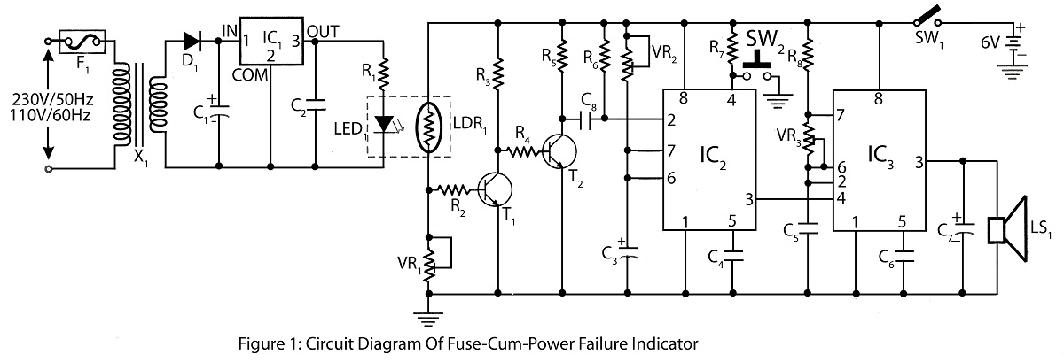
The Fuse Cum Power Failure Indicator utilizes a thermistor and a timer IC (NE555) in its circuit design. The circuit diagram includes a parts list for the fuse cum power failure indicator, which signals instances of power failure. The Fuse...
It is a simple circuit regulated power supply, based on the known LM 723, that drives a transistor Q1 [2N3055]. The regulation of voltage, of expense becomes with potentiometer R1 from 0v-30v DC roughly. In order to achieve 30...
This is a battery tester circuit. This circuit is used to indicate whether the level of a battery voltage is normal, under-voltage, or over-voltage. The battery tester circuit is designed to assess the voltage level of a battery and provide...
A circuit that allows a microcontroller to toggle a GPIO pin for shutting down the entire system, including the microcontroller itself. The system is normally powered down. When a momentary button is pressed by the user, power is restored....
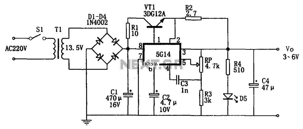
As shown in the figures, this is a practical adjustable power supply. It utilizes an integrated voltage regulator (5G14) in conjunction with a 3DG12A transistor for current spreading, providing an output voltage range of 3 to 6V. The rated...