
testing Board for PIC12F683
The project outlines the design and implementation of a learning board utilizing the PIC12F683 microcontroller, which is notable for its compact 8-pin configuration. The microcontroller operates within a voltage range of 2.0 to 5.5 V and is equipped with various features including a precision internal oscillator and multiple I/O pins that support interrupt-on-change functionality. The learning board is designed to facilitate experimentation and learning, providing access to the microcontroller's capabilities.
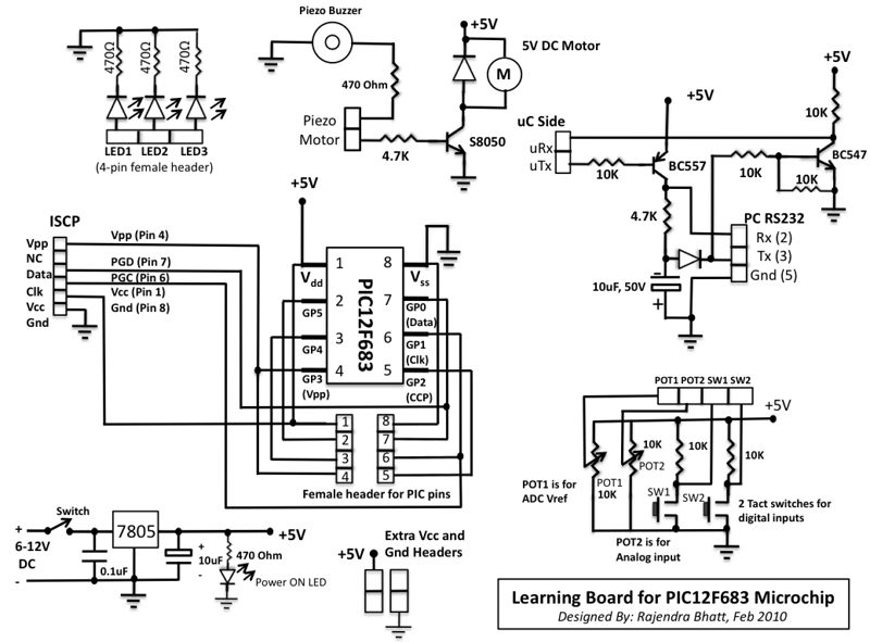
Power is supplied through a 9V DC input socket, regulated to +5V using a 7805 voltage regulator IC. This ensures stable operation of the microcontroller and associated components. The board includes three output LEDs and one power indicator LED, each connected with a 470Ω current-limiting resistor to protect the microcontroller pins. Input is facilitated through two tact switches and two potentiometers, one designated for analog input and the other to provide a reference voltage for the onboard ADC.
For serial communication, a transistor-based TTL to RS232 level converter is implemented, allowing for interaction with a PC. The design utilizes two transistors and additional components to achieve the necessary voltage levels, with the negative voltage sourced from the PC's RS232 port. The absence of a hardware UART in the PIC12F683 necessitates the use of a software UART for serial data transmission, utilizing designated GPIO pins for communication.
The circuit design also accommodates a DC motor, which is driven by an S8050 transistor. The microcontroller controls the transistor, allowing it to switch the motor on and off without directly sourcing the motor's current. Furthermore, a piezo-buzzer is included in the design, directly driven by a microcontroller pin through a series resistor.
The learning board features multiple female headers that provide access to all I/O pins of the PIC12F683, ensuring flexibility for various experiments. The tact switches are configured as active low, with their outputs defaulting to HIGH until pressed. Additional headers for Vcc and Gnd are also provided for convenience during experimentation.
In-circuit serial programming (ICSP) is supported through designated pins, allowing for easy reprogramming of the microcontroller using an ICSP programmer. The board layout is designed for ease of use, with clear access to all necessary components and connections, facilitating an effective learning environment for users interested in microcontroller applications. The overall design is compact, utilizing a general prototyping board measuring 8 x 12 cm, which enhances portability and ease of use in various educational settings.This microcontroller fascinated me a lot because I wanted to see what we can do with an 8-pin microcontroller (out of which 2 pins goes to power supply, so actually just 6-pins are left for I/O). So I thought of making my own learning board for this. In this project, I am first going to describe the learning board that I made, and then will demonstrate few experiments on it.
Some of the features of PIC12F683: Wide operating voltage range (2.0-5.5V). Precision internal oscillator (software selectable, 8 MHz to 125 Khz). 6 I/O pins with interrupt-on-change features. Four 10-bit A/D converters. Two 8-bit and one 16-bit timers. One Capture, Compare, PWM module. In-Circuit Serial Programming. Program Memory- 2048 words, SRAM- 128 bytes, EEPROM-256 bytes A 9V DC input socket with power on switch Regulated +5V power supply using 7805 IC 3 output LEDs and 1 power on LED 2 input tact switches 2 potentiometers: one for analog input and the other for providing reference voltage for ADC Transistor-based TTL-RS232 level converter for serial communication. A DC motor with a transistor driver. A piezo-buzzer As you see the output LEDs have 470? current limiting resistors in series so that a PIC pin can be safely drive them. The piezo buzzer is also driven directly by a PIC pin through a series resistor. The DC motor, however, is connected as a load to the collector of S8050 transistor as the required current to drive the motor cannot be supplied by the PIC port.
So, the PIC port can switch on the transistor by pulling its base HIGH and the collector current of the transistor provides the sufficient current to drive the motor. The TTL to RS232 level converter and vice-versa is achieved with two transistors and few other components.
The negative voltage required for RS232 level is stolen from the RS232 port of a PC itself. Note that there is no hardware UART inside PIC12F683, so the serial data transfer from the microcontroller to PC will be possible only through a software UART through any of GP0, GP1, GP2, GP4, and GP5 ports (GP3 is input only). The transmitter and receiver port on microcontroller side are denoted by uTx and uRx, whereas on the PC side are denoted by Tx and Rx, respectively.
The circuit diagram shows that the two input tact switches with the two potentiometer outputs and all the eight PIC12F683 pins are accessible through female headers. The tact switches are active low, i.e., under normal condition, a tact switch output is HIGH and when it is pressed, the output is LOW.
There are couple of extra headers for Vcc and Gnd terminals which may be required while doing experiments. The power supply circuit is the standard circuit of 7805 regulator IC. A power-on LED is connected across Vcc and Gnd with a 470? series resistor. The in-circuit serial programming (ICSP) of PIC12F683 can be done with two pins: ICSPDAT (pin 7), and ICSPCLK (pin 6).
The programming voltage, Vpp, should be provided to pin 4 of PIC12F683 while programming. All the required ISCP pins are available through a male header, so the PIC can be programmed through any ICSP PIC programmer. Make sure that the sequence of ISCP pins on the programmer side and our learning board match. Most of these features on the board are accessible through female header pins. None of the 6-I/O pins of PIC12F683 are hardwired to anything and they are accessible through header pins too.
The figures below show PIC12F683 pins, the type of female headers and jumpers used to make connection on the board, and the detail circuit diagram of the learning board. Only the ISCP pins are accessible through male header pins. The entire circuit is built on a 8 x 12 cm general prototyping board. 🔗 External reference
Related Circuits
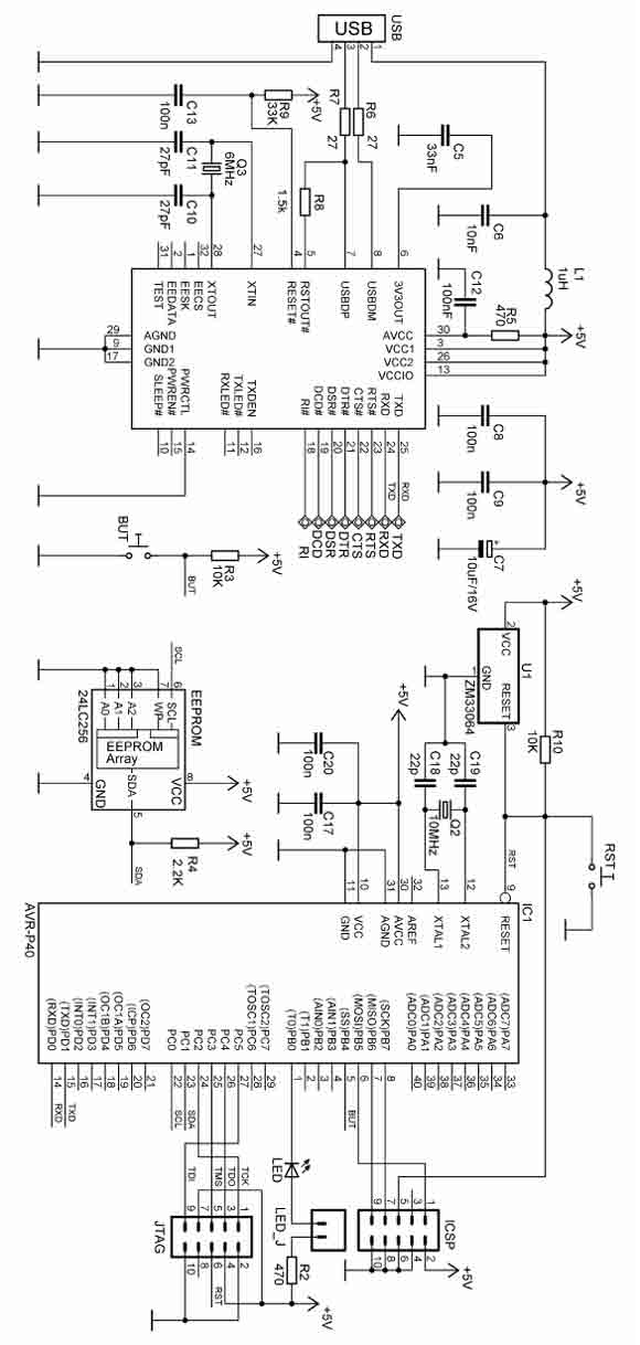
There are two ways to program AVR-P40-USB: with ICSP port and with JTAG port. To program via ICSP port you need serial port or parallel port AVR-ICSP programmer dongle (Olimex part # AVR-PG1B or AVR-PG2B). The serial port ICSP...
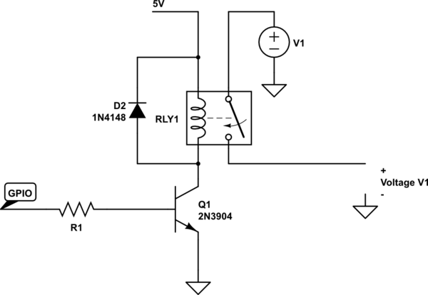
A couple of motors were salvaged from an old printer, and there is uncertainty regarding how to connect them to a breadboard and subsequently to a Raspberry Pi. A cobbler kit for the Raspberry Pi is available for this...
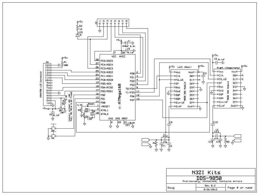
This project supports an LCD module (16x2 HD44780) and includes an AVR Micro ATMEGA168 programmed with demo/test code. It features a high-quality PCB made in the USA, which includes solder mask, plated through holes, and is RoHS compliant. The...
Here's PLL FM transmitter circuit from china. This circuit uses the familiar 2SC1971 for final power amplifier stage. The PLL controller of the FM transmitter use SAA1057 and PIC16F628 (download HEX file). More: If want to change the active...

The LM4550 is an audio codec designed for PC systems, fully compliant with PC99 standards, and performs the analog-intensive functions of the AC97 Rev2.1 architecture. It utilizes 18-bit Sigma-Delta analog-to-digital (A/D) and digital-to-analog (D/A) converters, providing a dynamic range...
Any microcontroller from the ATmegaXX8 family can be utilized, although investing a small amount in additional flash memory is advisable. A DIP socket is technically optional, but its absence is not recommended. A 28-pin DIP socket is somewhat uncommon;...