
The AA8V 6AG7 Amplifier
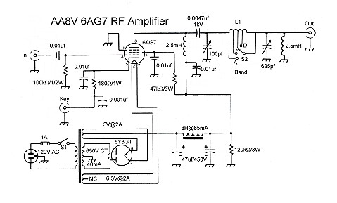
The circuit utilizes an input coupling capacitor to facilitate the passage of the input signal to the grid of the 6AG7 tube while simultaneously safeguarding the grid bias from being shorted to ground. This is crucial because a shorted grid bias can lead to overheating and potential damage to the tube. The capacitor's value is not critical; it must only ensure that its reactance at the lowest operating frequency remains significantly lower than the grid resistor's value. The grid resistor plays a dual role: it allows the grid bias generated by the cathode resistor to reach the grid and acts as a load for the input signal. Its value should be sufficiently high to avoid excessive loading on the input source while still permitting the necessary grid bias to pass through.
The cathode bias resistor is of utmost importance, as the cathode current flowing through it creates a voltage drop that establishes the grid bias. This bias must be carefully set to minimize the drive required by the amplifier while preventing tube overheating. Testing revealed that a value of 180 ohms maintains plate dissipation below the maximum threshold of 9 watts. Additionally, the cathode bias resistor introduces a negative feedback effect, which can be counterproductive. To mitigate this, a capacitor is connected from the cathode to ground, allowing the output signal to circumvent the cathode resistor and maintain the bias.
Keying the amplifier is achieved by interrupting the cathode return to ground, with a bypass capacitor included to filter any stray RF signals that may enter through the keying jack. The 6AG7 tube is designed for class A service, with a maximum plate dissipation of 9W, and is functionally similar to the 6CL6 tube but with a higher dissipation capacity.
In operation, the circuit supplies approximately 350 volts of DC plate voltage to the tube while extracting the amplified RF signal. A 2.5 mH plate RF choke allows DC to flow while blocking RF from returning to the plate supply. The 0.0047 µF plate coupling capacitor facilitates the passage of RF to the plate tank circuit while isolating the DC plate voltage. A 0.01 µF plate bypass capacitor further prevents any residual RF from affecting the B+ supply. The plate tank circuit, configured as a pi-network, effectively matches the high impedance of the tube's plate to the low impedance of the antenna and filters out unwanted harmonics, ensuring efficient signal transmission. The circuit's tuning is finalized with a 100 pF plate tuning capacitor, which adjusts the plate to resonance, optimizing performance across the intended frequency range.The input coupling capacitor allows the input signal to pass through to the grid of the tube while preventing the input source from potentially shorting the grid bias to ground. If the grid bias were shorted out, the 6AG7 would overheat and it would be destroyed. The value of this capacitor is not critical at all. As long as the reactance of the c apacitor at the lowest operating frequency (in this case 4. 5 ohms at 3. 5 MHz) is small compared to the value of the grid resistor, the circuit will operate correctly. The grid resistor allows the grid bias developed by the cathode resistor to pass through to the grid, while providing a load for the input signal. The value of this resistor is not critical. As long as it is high enough to prevent too much loading of the source, while still allowing the grid bias through, the circuit will operate fine.
The value of the cathode bias resistor is critical. Cathode current (sum of plate and screen currents) passing through this resistor causes a voltage drop across the resistor. This voltage drop is the bias applied to the grid of the tube. The bias is critical. In this amplifier the bias is chosen so that the amplifier requires the least amount of drive possible.
This means making the bias as small as possible, while preventing the tube from overheating. The various currents and voltages in the tube were measured while the value of this resistor was varied. 180 ohms was finally chosen as this kept the plate dissipation safely under the maximum value of 9 watts.
While the cathode bias resistor generates the tube bias, it also offers opposition to the signal that ultimately flows to the plate (the output signal). This causes negative feedback, which, in this case, is undesirable. The solution is to connect a capacitor from the cathode to ground. This allows the output signal to flow around the cathode resistor, without affecting the bias developed by the resistor.
The value of this capacitor is not critical. As long as the reactance of the capacitor at the lowest operating frequency (in this case 4. 5 ohms at 3. 5 MHz) is small compared to the value of the bias resistor, the circuit will be fine. The amplifier is keyed by opening the cathode return to ground. A bypass capacitor is connected across the key to prevent any stray RF that may enter through the keying jack from affecting the amplifier. The value of the capacitor is not critical. The 6AG7 is a power pentode designed for class A service. It is a metal tube with a maximum plate dissipation of 9W. Is is identical electrically to the miniature 6CL6 tube which was released in May of 1953, but it has a slightly higher plate dissipation than the 6CL6.
The higher plate dissipation allows for a slightly higher output than the 6CL6, given the same amount of drive. In an RF amplifier it is necessary to supply DC plate voltage to the tube (about 350 volts in this case) and at the same time extract the amplified RF that appears at the plate of the tube.
In the circuit at right, the 2. 5 mH plate RF choke allows the direct current from the plate supply (B+) to pass through it, while preventing the RF on the plate of the tube from flowing back through the plate supply. At the same time, the. 0047uf plate coupling capacitor permits the RF on the plate to flow though to the plate tank circuit while blocking the plate voltage.
The. 01uf plate bypass capacitor short circuits any residual RF that might have gotten through the plate RF choke and prevents it from reaching the B+ plate supply. The plate tank circuit is a pi-network that matches the high impedance of the plate to the low impedance of the antenna.
At the same time the circuit filters out undesired harmonics from the output signal. The signal from the plate enters through the 0. 0047 uf plate coupling capacitor. The 100 pf plate tuning capacitor tunes the plate to resonance. The band switch and tank coil provide the correct in 🔗 External reference
Related Circuits
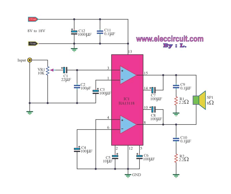
The amplifier circuit utilizes the HA13118 IC, a Hitachi component designed to deliver 18 watts of output power. This integrated circuit operates as a Class AB amplifier. The HA13118 IC is a versatile audio amplifier designed for high-fidelity applications, providing...

The amplifier utilizes a single MRF245 transistor and delivers 80 W of output power with a gain of 9.4 dB across the frequency range of 143 to 156 MHz. The circuit design for the amplifier featuring the MRF245 transistor is...
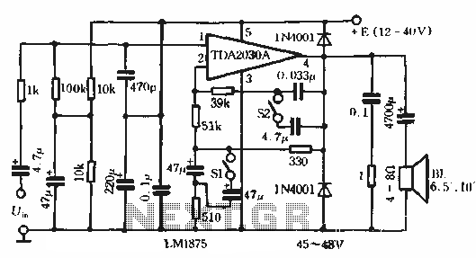
This circuit features bass boost compensation for a practical power amplifier. It is important to adhere to the specified parameters of the amplifier circuit elements. When switches S1 and S2 are disconnected, the bass boost function can be set...
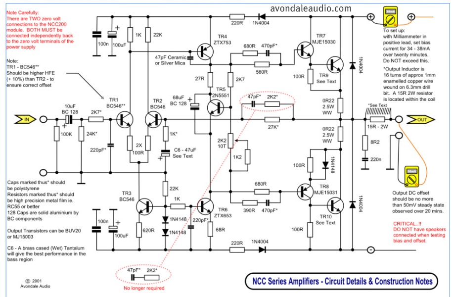
This is a simple circuit that features high-performance power amplifiers. The power amplifier is available as a PCB, along with a complete list of components. The described circuit utilizes high-performance power amplifiers, which are essential for applications requiring significant signal...
This small amplifier was intended to be used in conjunction with an electric guitar to do some low power monitoring, mainly for practice, either via an incorporated small loudspeaker or headphones. The complete circuit, loudspeaker, batteries, input and output...
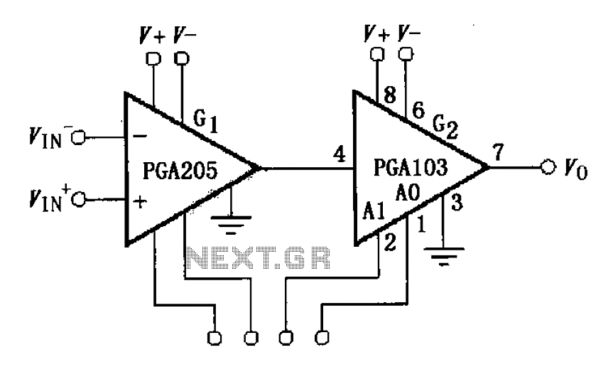
The circuit depicted in the figure comprises a PGA103 programmable gain instrumentation amplifier. This design utilizes the PGA205 and PGA103 in a cascading configuration, resulting in a total gain for the amplifier. The gain is determined by the product...