
Constituted by the PGA103 programmable gain instrumentation amplifier circuit diagram

The PGA103 is a high-performance programmable gain amplifier designed for use in precision applications. It features low noise and low distortion characteristics, making it suitable for amplifying weak signals in instrumentation systems. The cascading arrangement of the PGA205 and PGA103 enhances flexibility in gain selection, allowing for a wide range of amplification tailored to specific application requirements.
In this configuration, the PGA205 serves as the first stage of amplification, providing initial gain settings through its selectable options. The output from the PGA205 feeds into the PGA103, which further amplifies the signal based on its own gain settings. This method of cascading amplifiers not only increases the overall gain but also improves the linearity and bandwidth of the system.
The gain selection is controlled through digital logic inputs, enabling quick and precise adjustments based on the needs of the application. This feature is particularly beneficial in dynamic environments where signal levels may fluctuate, requiring real-time gain adjustments to maintain optimal performance.
Overall, the PGA103 and PGA205 combination offers a versatile solution for applications requiring programmable gain amplification, such as medical instrumentation, industrial sensors, and audio processing systems. The ability to achieve a maximum gain of 800 while maintaining signal integrity makes this circuit an excellent choice for high-fidelity amplification tasks. As shown in FIG constitute grounds PGA103 programmable gain instrumentation amplifier. This circuit uses the PGA205 and PGA103 cascading manner, the total gain of the amplifier gain is the product of two amplifiers, namely G G1G2. G1 1,2,4,8, G2 1,10,100, choose different logic inputs can choose different gain, maximum gain of up to 800 (other gains were 1,2,4,8,10,20, 40,80,100,200,400).
Related Circuits
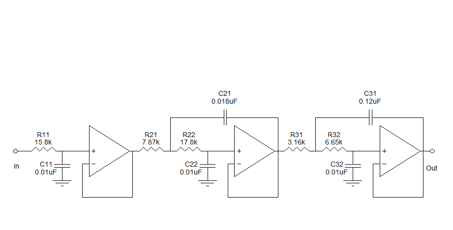
Assistance is needed to understand a schematic. Most components are clear, except for the triangular symbols which are likely operational amplifiers (op-amps). Clarification is required on their implementation and arrangement. The current diagram is intended for testing with a...
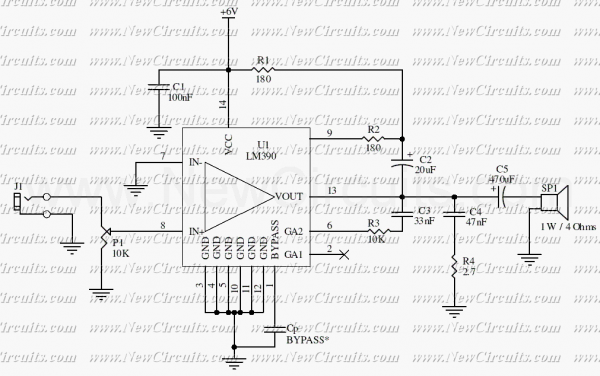
This circuit is a mono audio amplifier that will boost low frequencies as you see at the frequency response. The circuit is suitable for driving a subwoofer speaker for example. The output power of the circuit is about 1...
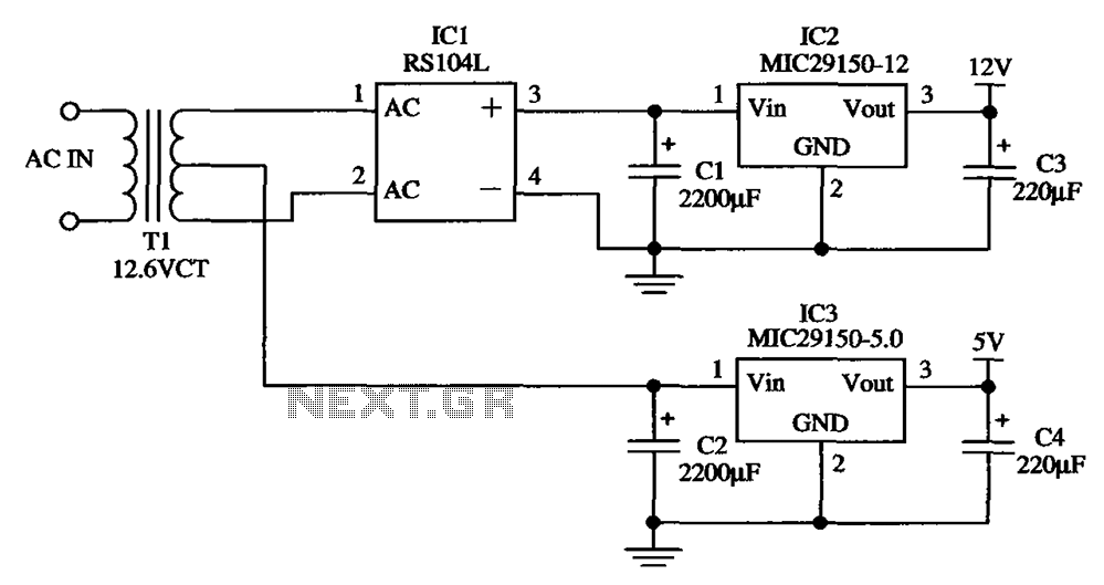
The low-cost dual output voltage regulator circuit is composed of two Micrel company regulators, the MIC29150-12 and the MIC29150-5.0. The dual output voltage regulator circuit utilizes the MIC29150 series from Micrel, which are low-dropout (LDO) voltage regulators designed for various...
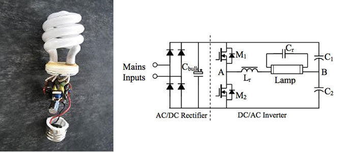
A circuit diagram for a 40W, 230V transistor-based electronic ballast is required. What steps are involved in designing an electronic ballast? An electronic ballast is a device used to regulate the current to fluorescent lamps and provide sufficient voltage to...
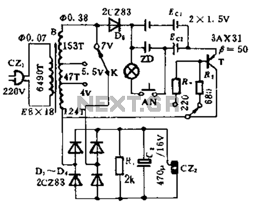
This circuit is designed for high current applications using nickel-cadmium rechargeable batteries, and it can also function as a general low-voltage DC power supply. The circuit consists of a charging section and a DC output section. K2 serves as...
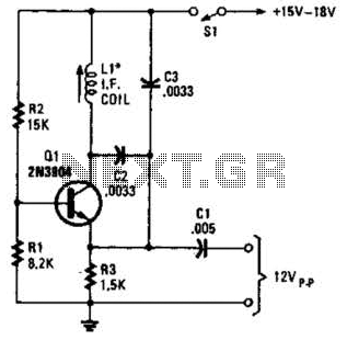
A simple oscillator for intermediate frequency (IF) alignment at 455 kHz can be useful in field testing or in scenarios where a standard signal generator is available. The inductor (L1) should resonate at the desired output frequency with the...