
The application circuit diagram of thermal conductivity gas sensor with RTD

The described sensor circuit employs a Wheatstone bridge configuration, which is ideal for precise measurements of resistance changes due to temperature variations. In this circuit, RA is configured as the sensing element, while RB serves to compensate for temperature fluctuations that may affect the measurement accuracy. The platinum resistors are chosen for their stable resistance characteristics over a wide temperature range, which is critical for applications requiring reliable thermal conductivity measurements.
The operational principle hinges on the fact that the thermal conductivity of gases changes with temperature. As the sensor's temperature increases, the resistance of RA alters, causing an imbalance in the Wheatstone bridge. This imbalance results in a measurable voltage output, which can be interpreted to quantify the concentration of hydrogen in the environment. Given that hydrogen exhibits a significantly higher thermal conductivity than air, the sensor can detect even slight variations in hydrogen concentration with high sensitivity.
To ensure the stability of the bridge voltage, precision components are utilized, and the circuit may include additional filtering or amplification stages to enhance signal integrity. The specified bridge voltage stability of 0.1% indicates that the circuit is designed to minimize drift and noise, thereby ensuring accurate and repeatable measurements. This level of stability is particularly important in applications such as gas detection and monitoring systems, where safety and performance are paramount.
Overall, the sensor circuit is engineered to provide reliable and accurate thermal conductivity measurements across a specified temperature range, making it suitable for various industrial and research applications.The principle of the sensor: when it is in high temperature (200 to 800 ƒ), the temperature of the sensor changes with the gas thermal conductivity, then the resistance of platinum resistor wire is detected. In the circuit, RA and RB are the platinum resistor wires, which are respectively used as detection device and temperature compensation ele
ment. Detection devices work according to temperature changes, so the bridge voltage requires a high stability. Compared to air, the hydrogen has larger thermal conductivity, which is easy to measure, therefore, the voltage stability of bridge is 0.
1%. 🔗 External reference
Related Circuits
At low output power, up to 18 W, the device functions as a standard BTL amplifier. When a greater output voltage swing is necessary, the internal supply voltage is increased using external electrolytic capacitors. This momentarily elevated supply voltage...

Inverters U1a and U1b are connected in a simple RC oscillator circuit. The frequency is determined by the values of R1, C1, C2, and the internal characteristics of the integrated circuit. As long as the circuit is oscillating, a...
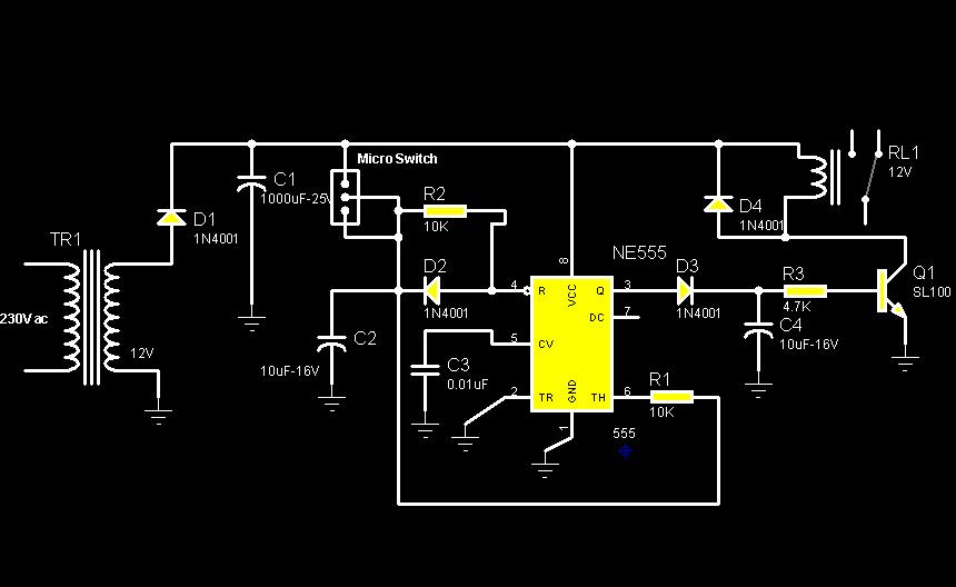
The circuit diagram illustrates a rotation sensor that activates a device, such as a motor or buzzer, when the circuit assembly is rotated. The design is based on the fundamental operation of a 555 timer. The rotation sensor circuit utilizes...
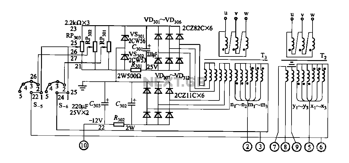
FGDF-3 is a three-phase low-temperature iron plating power supply circuit, while the KGDF-3 is a single-phase low-temperature iron plating power supply device that encompasses all the characteristics of the power supply unit. This design allows for an even distribution...
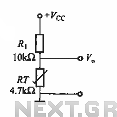
The basic application circuit for thermistors is illustrated. Figure (a) depicts a fundamental temperature measurement circuit. The accuracy of this temperature measurement is not high and is suitable only for applications with lower precision requirements. RT represents a positive...
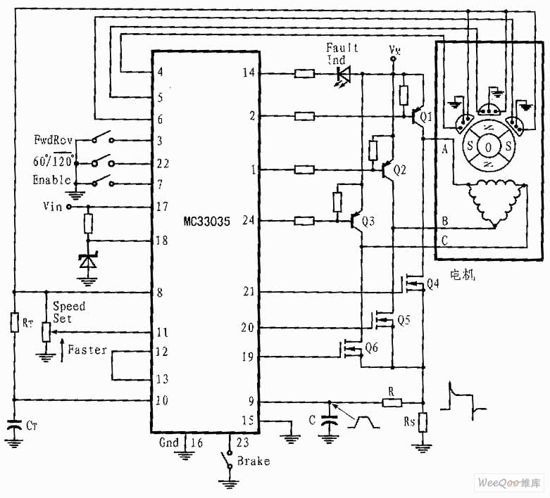
The presented three-phase application circuit features a motor controller circuit connection diagram that operates using a full-wave six-step method. The power switch is a Darlington PNP type, while the lower power switch is an N-channel power MOSFET. Each device...