
The "BEAM Stepper" drive circuit
Let’s assume that the top half of the driver is enabled. U1A & U1B along with R8, C1, and the input protection resistor R7 form a square wave oscillator. The outputs of U1A & U1B directly drive one coil of a bipolar stepper motor. More: The "BEAM Stepper" drive circuit A Duane C Johnson / Wilf Rigter joint effort Duane Johnson and Wilf Rigter came up with this interesting 74AC240-based circuit to drive small bipolar stepper motors (e.g., the ones in floppy drives): The 7
The 74AC240 is a high-speed hex buffer/driver with three-state outputs, primarily used in digital circuits for driving loads. In this specific application as a stepper motor driver, the circuit utilizes the device's capability to produce square wave signals that control the motor's coils. The configuration involves enabling either the upper or lower half of the buffer, allowing for a controlled sequence of energizing the motor coils, which is essential for stepper motor operation.
When the top half of the buffer (U1A and U1B) is activated, it generates an oscillating signal facilitated by the components R8 and C1, which form an RC timing circuit. This arrangement effectively creates a square wave oscillator that toggles at a specific frequency, determined by the values of R8 and C1. The input protection resistor R7 ensures that the inputs to the buffer are safeguarded against voltage spikes, thus enhancing the reliability of the circuit.
The outputs from U1A and U1B are connected directly to one of the coils of the bipolar stepper motor. As the square wave oscillates, it alternates the current through the motor coil, causing the motor to step in precise increments. The design is particularly effective for small bipolar stepper motors, such as those found in floppy drives, where precise control over position and speed is necessary.
The collaboration between Duane C. Johnson and Wilf Rigter has resulted in a practical and efficient circuit for controlling stepper motors using the 74AC240, demonstrating the versatility of this IC in various applications within the realm of robotics and automation. This circuit exemplifies the principles of digital electronics applied to motion control, showcasing how simple components can be combined to achieve complex tasks.The 74AC240 stepper driver works by alternately enabling each half of the buffer. Only one half can be enabled at a time. Let`s assume that the top half of the driver is enabled. U1A & U1B along with R8, C1, and the input protection resistor R7 form a square wave oscillator. The outputs of U1A & U1B directly drive one coil of a bipolar stepper motor. The "BEAM Stepper" drive circuit A Duane C Johnson / Wilf Rigter joint effort Duane Johnson and Wilf Rigter came up with this interesting 74AC240-based circuit to drive small bipolar stepper motors (e.g., the ones in floppy drives): The 7 🔗 External reference
Related Circuits

This circuit was designed to obtain a valve-like distorted sound from an electric guitar or other musical instrument. For this purpose a very high gain, three-FET amplifier circuit, was used. The output square wave shows marked rounded corners, typical...
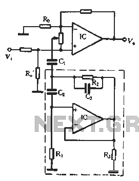
In the second equalization circuit connection method, it operates as illustrated in Figure 1-96. When the potentiometer wiper is moved to the inverting input terminal "a", the resonance impedance of the parallel combination of the feedback resistor RB reaches...
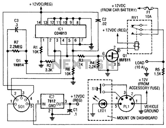
The power controller operates from the vehicle's accessory switch, allowing the load to receive power only when the ignition key is in the "on" position. A momentary pushbutton controls a load of up to 10 A using half of...
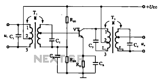
There are two resonant circuits in a double-tuned amplifier circuit, which consists of transformers T1 and T2 with primary and secondary coils that include parallel resonance capacitors. This circuit exhibits a resonance function and can be classified based on...
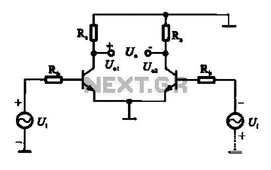
An amplifier circuit is designed to handle an assumed input consisting of two equal and opposite polarity signals, known as a differential mode signal. The two tube collector currents, Ic and IC7, are balanced in such a way that...
The LM1036 is a DC-controlled circuit designed for adjusting bass, treble, balance, and volume in stereo applications, particularly in car radios, televisions, and audio systems. An additional control input enables the implementation of loudness enhancement. Four control inputs facilitate...