
The Bean-Counter AM Transmitter
The circuit design is a sophisticated adaptation of the original Muntz transmitter, enhancing its capabilities while addressing inherent limitations. The inclusion of a 6AU6 pentode as an audio preamplifier stage significantly boosts the circuit's performance, allowing it to handle a wider range of input signals effectively. This improvement is crucial for applications where audio fidelity is paramount, particularly in environments utilizing vintage AM receivers. The negative feedback mechanism not only aids in achieving linear modulation but also stabilizes the overall performance of the transmitter, ensuring consistent sound quality across various operating conditions. The careful selection of components, such as the germanium diodes and the loop topology for the tank inductor, further optimizes the circuit's efficiency and harmonic performance. Overall, this enhanced design represents a significant advancement in the functionality of the Muntz transmitter, making it suitable for modern audio applications while retaining the charm of vintage technology.The Muntz one-tube design can be considerably improved by adding an audio preamplifier stage. This will give improved sensitivity, and thus give full modulation with lower-level signal sources (such as some older CD players, ceramic phono cartridge, etc. ). Furthermore, the use of negative feedback around the whole transmitter improves linearity and allows for deeper modulation levels without distortion. While the one-tube transmitter works well for such a simple circuit, it does have significant drawbacks. One problem is that the input sensitivity is a too low for some common input sources. Another is that linearity could be improved; the one-tube basic transmitter has a somewhat strident audio quality at higher modulations because of harmonics introduced by the non-linearity.
Adding a second tube (as an audio preamp) solves the first problem, and improves the second. This is essentially "The Muntz" with a preamp stage, consisting of a 6AU6 pentode. This gives lots of gain, in fact enough for even high-output microphones. However, since this circuit is most useful to us as a line-level amplifier (in the range of 0. 1 to 2 volts RMS), we can readily afford to trade some of this gain for fidelity by adding an overall negative feedback loop. The network around the pair of germanium diodes full-wave rectifies the modulated RF output, just like the detector in a radio receiver.
This recovered audio is fed back, out of phase, to the input of the preamp. While germanium diodes are less linear than vacuum diodes, this is mollified by the fact that they`re inside the feedback loop. We haven`t changed anything in the RF section, so the output power of this version is still only 3 milliwatts, but plenty for in-house broadcasting (or if your linear has enough gain).
What`s more, the circuit was tweaked to help reduce harmonic output. The tank inductor in the tuned circuit was wound in a loop topology instead of solenoid, yielding a much higher inductance for a given wire length, and hence a higher Q to help reduce harmonics. Tuning proceeds just like "The Muntz", except that you`ll find it much easier to discern the clipping point due to the negative feedback loop on the audio.
The feedback method is a bit unconventional, and relies on the input source to be of relatively low impedance. However, it works very well, linearizing the modulated signal nicely. The improvement in sound is quite noticeable, especially when listening on good vintage AM receivers.
The cathode of the 6AU6 is unbypassed, giving some local negative feedback. Though you might be tempted to bypass it, this isn`t recommended since it can result in instability of the overall feedback loop. Note that this overall feedback system doesn`t have an isolating cap to the input (grid) of the 6AU6.
This is so that the DC component is also fed back, along with the audio component. This helps to overcome the load dependance of the un-isolated oscillator. If the average RF level decreases due to changing load conditions, the DC voltage feedback decreases also (goes more negative), decreasing the transconductance (and therefore voltage gain) of the 6AU6, and effectively reducing the modulation to compensate. (You might think that a remote-cutoff pentode such as 6BA6 would be preferred, but in practise the variance in DC voltage is not enough to have a significant effect using the 6BA6, etc.
) The RF choke in the cathode of the oscillator has also been eliminated. The crystal oscillator is a bit more finicky using a resistor instead of a choke, but with the values shown it`s stable and reliably self-starting. This approach also slightly reduces the maximum modulation depth from 90% to about 85%, which is still quite acceptable for in-house use.
Here`s a pic of the "Bean Counter. " Since I was counting beans to build this one, I finally used up a rather ugly Radio Shack project box that`s been kicking around here for eo 🔗 External reference
Related Circuits
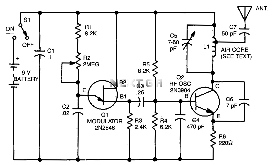
The range of this transmitter is approximately 50 feet with a short whip antenna. The tone generator consists of a unijunction transistor (Q1) along with resistors R1, R2, R3, and capacitor C2. Transistor Q1 operates by pulsing on and...
The circuit was designed to operate a frequency modulation voice transmitter over the FM band within the VHF frequency range. The transmitter is an electronic device. The frequency modulation (FM) voice transmitter circuit operates within the VHF (Very High Frequency)...
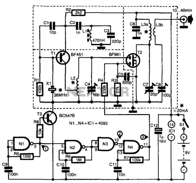
The transmitter is specifically designed for radio amateurs to function as a radio beacon, delivering a high-quality signal devoid of unwanted harmonics. Transistor T1, in conjunction with crystal X1, serves as a 36-MHz oscillator. Filter L1/C3 prevents the circuit...
The frequency range is 100-108 MHz. The circuit is a mono circuit that accepts audio input from either a microphone or another source. The input impedance is 1 MΩ, with an input sensitivity of 5 mV and a maximum...
This is an IR transmitting circuit which can be used in many projects. This IR transmitter sends 40 kHz carrier under computer control. The circuit can be controlled using any TTL or RS-232C level control signal which makes the...
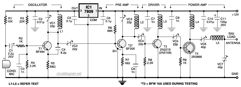
A four-stage FM transmitter circuit diagram utilizes four radio frequency stages: a VHF oscillator designed around the BF494 transistor (T1), a preamplifier based on the BF200 transistor (T2), a driver built with the 2N2219 transistor (T3), and a power...
Warning: include(partials/cookie-banner.php): Failed to open stream: Permission denied in /var/www/html/nextgr/view-circuit.php on line 713
Warning: include(): Failed opening 'partials/cookie-banner.php' for inclusion (include_path='.:/usr/share/php') in /var/www/html/nextgr/view-circuit.php on line 713