
DC supply voltage the more limited indication circuit
The described circuit employs a voltage monitoring system that utilizes light-emitting diodes (LEDs) to provide visual indicators of the battery or storage pool voltage levels. The circuit is designed to operate within specific voltage thresholds to protect the storage pool from over-discharge and over-charge conditions.
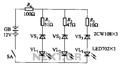
At the lower voltage threshold of 10.2V, the activation of the yellow LED (VLi) serves as a warning signal, alerting users that the voltage has fallen below a critical level. This condition indicates that the storage pool's capacity is nearly depleted, and further discharge could lead to irreversible damage or reduced lifespan of the storage cells.
Conversely, when the voltage exceeds 16.2V, a combination of yellow (VLi), green (VL2), and red (VLa) LEDs illuminate. This multi-LED indication serves to inform the user that the voltage is in an overcharge condition. The red LED specifically emphasizes the urgency of the situation, prompting immediate action to either stop charging or to reduce the charging current to prevent potential damage to the storage pool.
In the voltage range between 10.2V and 16.2V, both the yellow and green LEDs are activated. This state indicates that the system is operating within a safe and acceptable voltage range, allowing for normal charging and discharging operations. The green LED typically signifies that the system is functioning properly and that the voltage level is stable.
The circuit can be implemented using a voltage divider to monitor the voltage level, coupled with a comparator circuit that triggers the appropriate LEDs based on the detected voltage. The use of resistors and possibly a microcontroller can enhance the precision of voltage detection and LED control, allowing for customizable thresholds and additional features such as alarm signals or communication with other system components.When the supply voltage drops below 10. 2V, the yellow light emitting diode VLi light, suggesting that storage pool can not continue to discharge. When the voltage exceeds 16. 2V, the yellow, green and red light-emitting diodes VLi ~ VLa are light, suggesting that must immediately stop charging or reduce the charging current. When the voltage is within 10.2-16. 2V, the yellow and green light-emitting diode VLi, VL2 light.
Related Circuits
Access to the resistors was available, and measurements indicated an open circuit when disconnected from any ground or input source. The circuit in question involves resistors that have been verified for accessibility. When measured in isolation—meaning they are not connected...
This page is provided to the domain owner free by Sedo's Domain Parking. Disclaimer: The domain owner and Sedo maintain no relationship with third-party advertisers. References to any specific service or trademark are not controlled by Sedo or the...
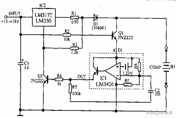
A lithium-ion battery charging circuit is illustrated above. Initially, when charging begins, if the battery voltage is below 8.4V, the output of IC1 is inactive. As a result, Q2 remains off, and the LM317 operates in constant current mode....
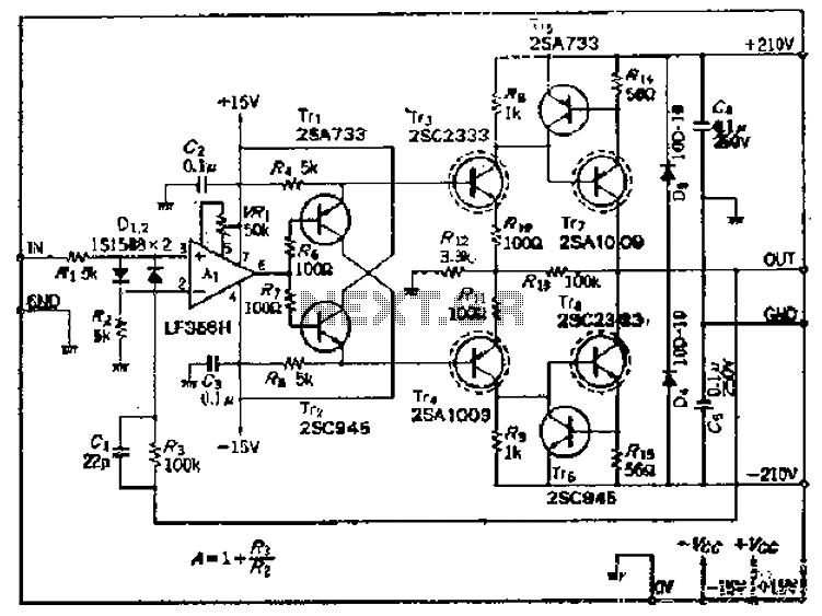
This amplifier circuit operates with an OP amplifier that is power-driven, which leads to the presence of floating voltage errors and necessitates a high-pressure booster for transistor protection. The circuit utilizes a mutual feedback configuration, connecting to the output...
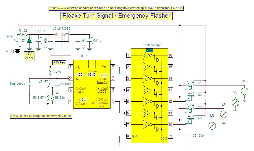
IR appliances use pulses (control signals) sent over a modulated IR carrier wave. The carrier wave may be modulated at various frequencies, 36-38KHz being the most popular. Some Satellite receivers use even higher frequencies than this. The IR1 remote...
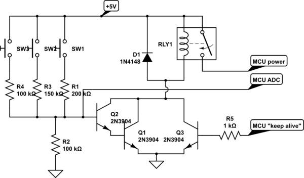
A circuit is being designed that utilizes a combination of switches and resistors to enable a microcontroller to identify which switch has been pressed based on the voltage read, and subsequently perform a switch-specific action. The proposed design incorporates...