
Current-tampering circuit
The described circuit effectively monitors current flow and provides a safety mechanism to disconnect the power supply in case of overload or theft. The use of a Triac (VTH) for control allows for efficient switching, while the relay (K) serves as a reliable means of cutting off power. The system is designed to be user-friendly, with a reset button that enables the restoration of power once the overload condition has been addressed.
The choice of components, particularly the relay and the transformer, is crucial for ensuring the circuit operates reliably under various load conditions. The JQX-4 relay is suitable for handling moderate loads and can be configured to enhance its capacity through parallel connections of its contacts. The 3CTSIB Triac is selected for its ability to handle AC loads effectively, providing a robust solution for the control mechanism.
The design emphasizes safety and ease of use, with the anti-interference measures incorporated into the trigger circuit to prevent false triggering due to electrical noise. This is especially important in environments where electrical fluctuations may occur. Additionally, the precise matching of TA1 and TA2 parameters is essential to maintain the integrity of the current sensing mechanism, ensuring that the system can accurately detect overload conditions without false alarms.
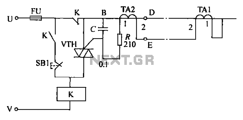
Overall, this circuit provides a comprehensive solution for monitoring and controlling electrical loads, with a focus on user safety and operational reliability. Circuit current is greater than the load carried by the rated current meter, the user immediately cut off the power supply to be subtracted overload, press the reset button to restore power, production of simple, convenient and feasible. Circuit shown in FIG. AC relay K is controlled by the Triac VTH. TA1 and TA2 end phase of the same name, in the pass when crossing the wire segment BD current meter current equal, TA1 and TA2 induced voltage equal to the secondary side. TA1 and TA2 1 no voltage between terminals, VTH is not turned on. K release, K normally closed contacts for power users. However, in the case of stealing, BD segment of a wire through the current meter current unequal, TA and TA2] two secondary side voltage induced errand VTH trigger conduction.
K pull its normally closed contacts cut off the users power supply circuit; while K is closed, so that K stays energized. Electrical control officers to be opened and open the rear cover, press the reset button after SB, K is not released, the user restore power.
VTH trigger circuit C has anti-interference effect, device malfunction fat only; R trigger current role is limited to avoid damage to the VTH trigger knot. Component selection: Relay K optional AC 220V JQX-4 type of small power relays, the normally 6ij several contacts in parallel can be increased load capacity.
VTH available 3CTSIB. rAl and TA2 parameters should be very consistent, otherwise malfunction when the current is large. Production time - core toroidal core is preferably selected, the power cord can pass therethrough as the primary side, with the appropriate wire wrap around one hundred turns as the secondary side.
Related Circuits
This radio receiver can operate with any of the following transistors: ZN414, MK484, or TA7642. The radio receiver circuit is designed to utilize a variety of transistors, specifically the ZN414, MK484, and TA7642, which are commonly used in low-power AM...
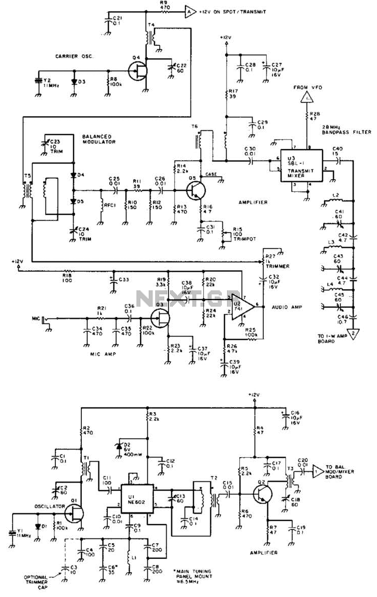
Using a Motorola MC2833 one-chip FM transmitter, a few support components, and an MPF6660 FET RF amplifier, this transmitter delivers approximately 3 W into a 50-ohm load. It is capable of operation over a frequency range of about 29...

The term "pentester" refers to a penetration tester, individuals who assess security vulnerabilities. Many high-end hotels globally depend on keycard locks for securing hotel rooms. However, recent incidents of theft have shown that these locks may not be as...

Daylight shutoff; the schematic has been updated but is not shown here. The daylight shutoff circuit is designed to automatically turn off lighting systems during daylight hours, thereby conserving energy and extending the lifespan of the lighting fixtures. Typically, this...
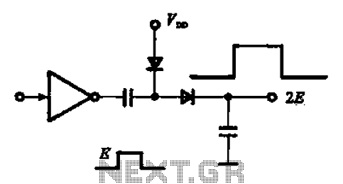
A pulse booster circuit is utilized to increase the pulse amplitude. The structure illustrated in figure (a) of the circuit can output a pulse amplitude that is twice that of the input. Figure (b) of the circuit can achieve...
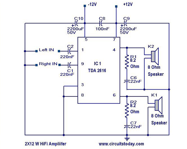
A simple Hi-Fi amplifier circuit diagram with a schematic for creating an audio amplifier, designed using the TDA 2616 integrated circuit (IC), which is a stereo power amplifier. It is suitable for use with radios, tape players, and televisions,...