
the dc motor circuit
The basic DC motor circuit allows for a simple on/off control of the motor. By connecting the battery to the motor through the alligator leads, the motor can be activated or deactivated based on the connection of the leads. However, for applications requiring direction control and speed modulation, the H-bridge circuit is essential.
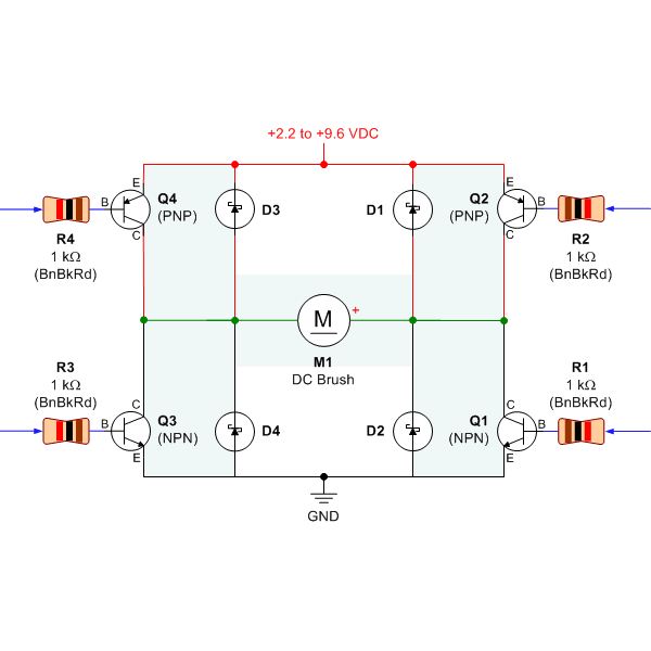
An H-bridge consists of four switches (typically transistors) arranged in a bridge configuration. By controlling the states of these switches, the current flow through the motor can be reversed, allowing for bidirectional control. For instance, turning on switches S1 and S4 while turning off S2 and S3 will cause the motor to rotate in one direction. Conversely, activating S2 and S3 while deactivating S1 and S4 will reverse the motor's direction.
In addition to direction control, the H-bridge can also facilitate speed control through pulse-width modulation (PWM). By varying the duty cycle of the PWM signal applied to the transistors, the average voltage and current supplied to the motor can be adjusted, thereby controlling its speed.
In summary, while a basic DC motor circuit suffices for simple applications, an H-bridge circuit provides the necessary functionality for advanced control of DC motors, enabling both direction and speed modulation essential for mobile robotics.Choosing the right DC motor is critical when building mobile robots. Testing DC motors is an easy process and can be done by building a simple DC motor circuit. All that is required to build this circuit is a DC motor, a battery power source of at least 3 V, and red and black alligator leads. To build the circuit, the red alligator lead is connected to the positive terminal of the battery and motor, whereas the black alligator lead is connected to the negative terminal of the battery and motor.
In order to control the functioning of a DC motor, a specialized DC motor circuit can be used, such as an H-bridge. The H-bridge circuit design is an array of transistors that work along with resistors and diodes to command a DC motor..
🔗 External reference
Related Circuits
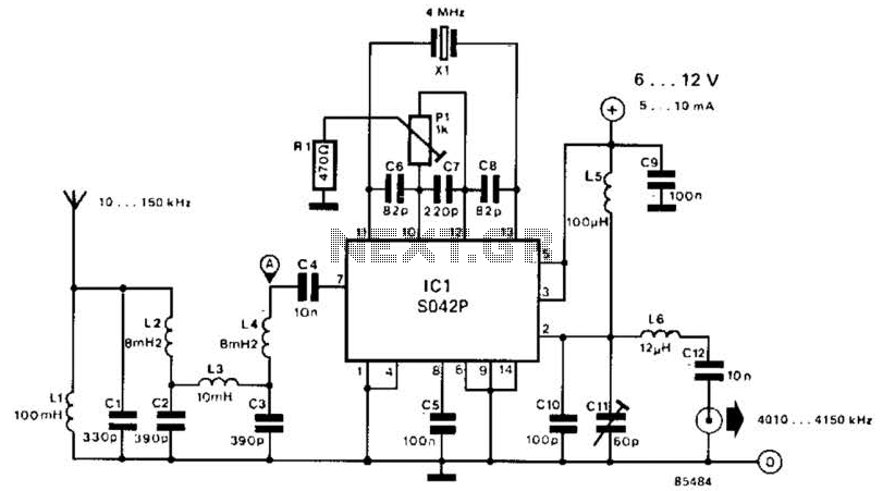
This converter shifts frequencies from 10 kHz to 150 kHz up to 4.01 to 4.15 MHz, suitable for use with a shortwave receiver for very low frequency (VLF) reception. A 4 MHz local oscillator frequency is utilized, and the...
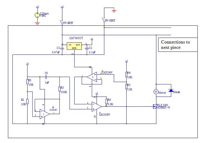
THE CUBE is a three-dimensional jigsaw puzzle that features a unique mechanism where a puzzle piece vibrates for approximately one second when it is correctly placed in the puzzle. This functionality is achieved through an electrical design that completes...
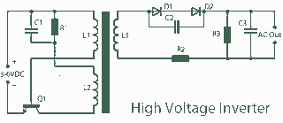
A 3V to 1000V inverter circuit has been constructed, but it is not functioning as intended. The creator seeks expert assistance to identify potential errors in the circuit design. Additionally, there is uncertainty regarding the transformer construction, as the...
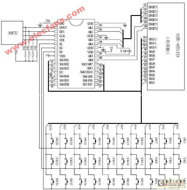
The ET6201 is a LED display control drive circuit with a duty cycle of 1/7 to 1/8. It features 11 segment output gates and 1 segment/gate output, along with a display memory, control circuit, and key scanning circuit, which...
The controller consists of a liquid level sensor, a trigger controller, and a step-down rectifier circuit. The water level detection poles labeled a, b, and c form a bias circuit, functioning as a water level detector with components W1,...
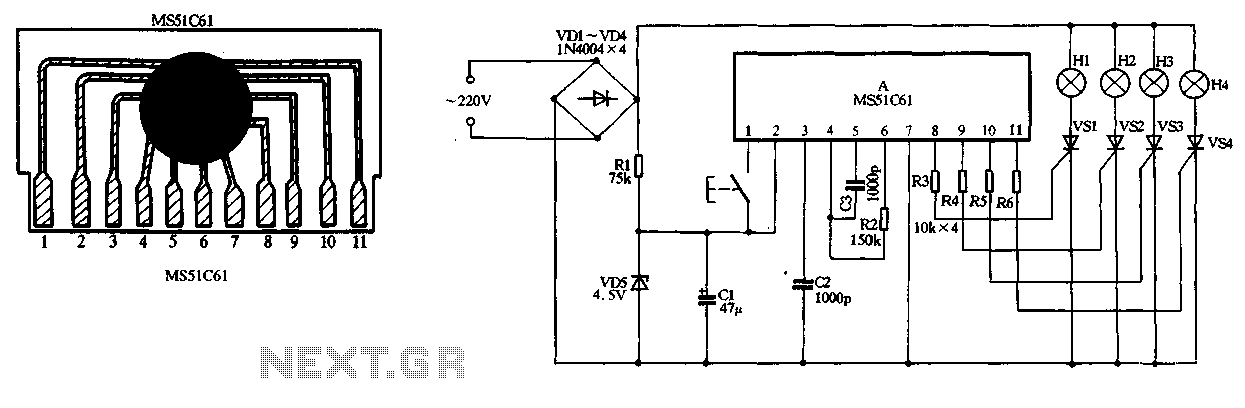
The circuit utilizes a 220V AC input, which is converted to DC using a VD1-VD4 bridge rectifier. This rectified voltage is used to power four lights (H1 to H4). The circuit also includes a resistor (R1) for voltage limiting...