
The dual-way control SCR liquid level control circuit
The circuit operates by monitoring the water level through the three detection poles. The poles are strategically placed at different heights to provide a range of water level detection. The bias circuit is established using resistors R1, R2, and R3 in conjunction with the water level sensor W1. The output voltage from the detection poles is compared to a reference voltage level derived from the supply voltage VDD.
When the water level is above pole b, the voltage across R3 remains sufficiently high, preventing the 555 timer from triggering. However, as the water level drops below pole b, the voltage divider effect created by the resistors results in a voltage that falls below the threshold of 1/3 VDD. This triggers the 555 timer, which is configured in a monostable mode, leading to a change in its output state.
The triggered output from the 555 timer activates the SCR (Silicon Controlled Rectifier), which allows current to flow through the load circuit. This mechanism can be utilized for various applications such as activating a pump to refill the water tank or turning on an alarm system when water levels are critically low. The step-down rectifier circuit ensures that the control circuit operates at a safe voltage level, providing the necessary power for the entire system while protecting sensitive components from over-voltage conditions.
In summary, this circuit effectively combines a liquid level detection system with a control mechanism that can respond dynamically to changes in water levels, demonstrating a robust solution for automated water management systems.See as the figure, the controller consists of liquid level, trigger controller and step-down rectifier circuit, etc. The water level detecting poles of a, b and c compose the bias circuit as the water level detector with W1, R1, R2 and R3.
When the water level is below b, Vp-b?R3×VDD/?Rw1+R1+R2+R3?<1/3VDD, 555 is offset, SCR is triggered and conduct.. 🔗 External reference
Related Circuits
This is a measurement I did on a FM receiver (MC3372). I have plotted the output DC-bias as a function of the IF (Intermediate Frequency) frequency. At 455kHz you can see that I have 5.5V DC bias. When I...
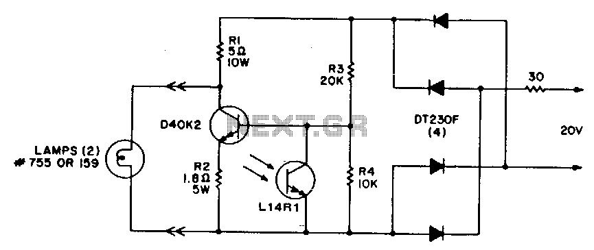
This circuit offers a cost-effective method for controlling light levels. Power for the circuit is derived from a relatively high source impedance transformer or motor windings, which are typically used to drive low-voltage lamps in these applications. It is...
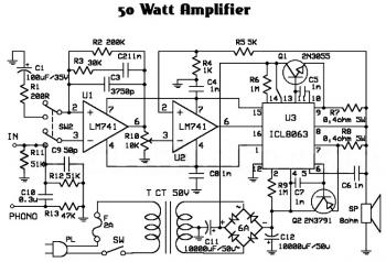
An audio amplifier is an electronic device designed to amplify low-power audio signals, which primarily consist of frequencies ranging from 20 Hz to 20,000 Hz, the human range of hearing. This amplification is necessary to drive loudspeakers and represents...
This circuit operates at potentially lethal 220V AC mains voltage. The circuit should be built and used only by individuals who know how to safely work with such dangerous voltages and how to construct the circuit to ensure safety....
SPI Integrated Circuit Bus, IC Buses, an IC, Chip-to-Chip Bus Serial Peripheral Interface, Integrated Circuit Bus types, and IC Bus Electrical Interface Descriptions. The Peripheral Interface (SPI) circuit is a. The Serial Peripheral Interface (SPI) is a synchronous serial communication...
The RF power amplifier circuit described here utilizes the transistors 2SC1970 and 2N4427. This FM RF amplifier operates within the frequency range of 88-108 MHz, delivering an output power of approximately 1.3W from an input driver of 30-50mW. The...