
mk484 am radio circuit design project

The MK484 AM radio circuit is designed to provide efficient reception of amplitude-modulated (AM) signals. The RF amplifier stage enhances weak incoming signals, improving overall sensitivity and selectivity. The detection circuit demodulates the AM signal, allowing audio frequencies to be extracted for further processing. The automatic gain control (AGC) circuit ensures consistent audio output levels by adjusting the gain of the RF amplifier in response to varying signal strengths, thus preventing distortion during strong signal reception.
The circuit's high input impedance of 4 MΩ is beneficial in minimizing loading effects on the antenna, allowing for better signal capture. Operating over a frequency range of 150 kHz to 3 MHz enables the circuit to cover the standard AM broadcast band, making it versatile for various AM radio applications.
The MK484 operates efficiently on a low DC supply voltage, making it suitable for portable and battery-operated devices. With a typical voltage of 1.4 V and a low current drain of 0.3 mA, the circuit is optimized for energy conservation, prolonging battery life in handheld radio receivers. The simplicity of the design, requiring only a few external components, facilitates easy integration into various electronic projects, making it an excellent choice for hobbyists and engineers alike.This MK484 AM radio circuit provides a complete solution including : RF amplifier, Detection and AGC circuit (automatic gain control ), which requires only a few external components to give a high quality AM Tuner. The circuit has an input impedance of 4Mohms and operates over a frequency range of 150KHz to 3MHz. The IC will run with DC supply bet ween 1. 1V and 1. 8V typical 1. 4V and a current drain of 0. 3mA makes it suitable for battery operation. 🔗 External reference
Related Circuits
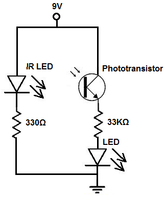
There are two methods to construct a proximity detector. The first method involves mounting the infrared (IR) LED and the phototransistor so that they face each other. In this configuration, the infrared light emitted by the IR LED is...

It is essential to draw a circuit using a layout and conventions that are universally recognized. In electronic circuit design, adherence to standardized symbols and layout conventions is crucial for effective communication among engineers and technicians. A well-drawn schematic diagram...
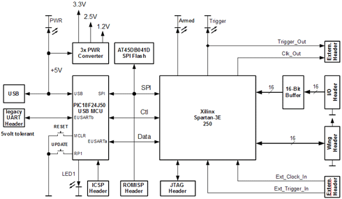
The Openbench Logic Sniffer is an open-source logic analyzer designed to support the SUMP logic analyzer software at minimal cost. Source and design files can be downloaded from the Gadget Factory project page. The project originated from discussions in...

The display circuit is utilized in a typical digital massager. At the heart of the control circuit is the microprocessor EM78156, which receives manual operation instructions. It triggers two transistors to supply voltage to the DC motor (A +,...

The intellectual wireless signal transducer is designed for major transducer applications and typical sensor output signal designs. It is essential to first analyze the outgoing signals from the transducer. Typically, the output of the transducer is a standard electric...

In the previous post, the primary principles of the switching power supply were discussed. Essentially, an oscillator drives a transformer with a ferrite core at a relatively high frequency, thereby minimizing the size, weight, and cost of power supplies....