
Automatic Frequency Control FM reciever
More info about the AFC regulation. Let's have a look at the frequencies for this receiver. The top figure shows the spectrum. At fRF you have the radio signal you want to receive. Since the IF (Intermediate Frequency) of the receiver is 455kHz, the fVCO can be ± 455kHz from the fRF. In both cases, you will receive the signal. Let's focus on the lower side and look at the bottom figure. Imagine that something has made the IF increase by +10kHz. The IF is defined as the frequency from the fRF, and with a +10kHz increase, the deviation goes to the left. The short blue line shows the deviation. The long blue line shows the new receiving frequency, and as you can see, we miss our RF signal. From the earlier measurements, it was found that +10kHz IF will increase the Vbias. If the Vbias increases, the capacitance in the varicap will decrease, and that decrease will make the fVCO increase in frequency. If the oscillator (fVCO) increases, the blue line will be pulled to the right and back to be locked to the original black fRF. This regulation will continue as long as the IF stays within the ± 20kHz (locking range).
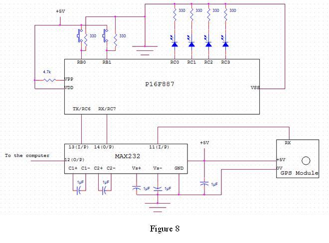
The described FM receiver circuit, based on the MC3372, operates effectively within a specified intermediate frequency (IF) range of 455 kHz. The output direct current (DC) bias is critical for maintaining optimal performance, with a nominal value of 5.5 V at the center frequency. The circuit employs a voltage-controlled oscillator (VCO) that utilizes a varicap diode (BB132) for frequency modulation. The varicap's capacitance changes in response to variations in the DC bias, which is influenced by the incoming radio frequency (RF) signal and the automatic frequency control (AFC) mechanism.
The AFC unit consists of a low-pass filter, comprised of a potentiometer (pot1), a resistor (1 kΩ), and a capacitor (1 µF), which smooths the output DC bias from the audio section. The tuning circuit includes a fixed inductor (L1) and a variable capacitor (C2), allowing for adjustments across a wide frequency spectrum. The RSSI output provides an indication of the incoming RF signal strength, which is essential for optimizing reception.
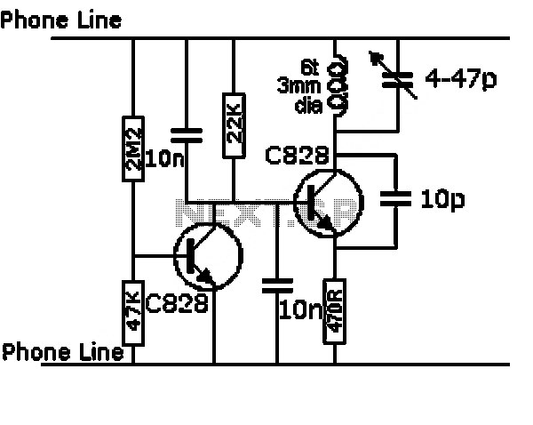
The AFC regulation operates by monitoring the IF, which can shift due to variations in the incoming RF signal. For instance, if the IF increases by 10 kHz, the resulting change in DC bias will prompt the VCO to adjust its frequency accordingly, maintaining lock on the desired RF signal. This feedback loop continues as long as the IF remains within the ±20 kHz range. The tuning capacitor (C2) can be adjusted to modify the feedback magnitude, with a recommended value of approximately 12 pF for effective locking of RF signals. This overall design ensures reliable reception and stable performance across the intended frequency range.This is a measurement I did on a FM receiver (MC3372). I have plooted the output DC-bias as function of the IF (Intermediate Frequency) frequency. At 455kHz you can see that I have 5.5V DC bias. When I change the IF frequency the bias will also change in both ways. This bias will work at 455kHz +/- 20kHz (linear are). If you go outside this range the filter is self will reject the frequency. The charper filter you use the smaller AFC range you got. Now imagin I want to receive at 100MHz. I tune my receiver to (100MHz - 455kHz = 99.545MHz) and I receive the radio station. With perfect tuning the DC bias will be 5.5V DC and I will have an AC audio signal also. If I now change the VCO by decresing the frequency with 20kHz the IF will also decrease with 20kHz and my DC bias will dropp to 5.0V according to my measurements. The reception will be bad. The output AFC filter is connected to the VCO and inside the VCO is a varicap. The varicap will now change its capacitance because of the voltage dropp. When the varicap change capacitance the VCO will increase in frequency until the IF frequency is back to 455kHz. The schematic show you a basic receiver circuit. L1 and C1 is the tuning part (VCO). L1 is fixed so the tuning is done with C2 which is a tunable capacitor. I have choosen L1 so you can use it in a wide frequency spectrum. The RSSI output indicates the strength of the incoming RF signal. Audio output is a low level output which need to be amplified in an audioamplifier. The few components in the dashed red box is the AFC unit. The DC bias from the audio output is smothed out by the filter (pot1 + 1k + 1uF). The bias will then regulate the capacitans in the varicap diod BB132 Since the varicap and the tunable capacitor C2 are parallel to C1 the tuning frequency will change according to the feedback of the bias voltage.
You have now a regulating system to keep the VCO locked to the RF signal. With the capacitor C2 and the pot1 you can set the magnitude of the regulating feedback. A high value of C2 will make large frequency change of the VCO. You will have to experiment to find good locking. It is not so critical. About 12pF of C2 gave me good locking of RF signals. More info about the AFC regulation Lets have a look at the frequencies for this receiver. The top figure show you the spectrum. At fRF you have the radio signal you want to receive. Since the IF (Intermediate Frequency) of the receiver is 455kHz, the fVCO can be ± 455kHz from the fRF. In both case you will receive the signal. Let's focus on the lower side and look at the bottom figure. Imagin that something has made the IF increase with +10kHz. The IF is defined as the frequency from the fRF and with a +10kHz increase the deviation goes to the left.
The short blue line show you the deviation. The long blue line show you the new receiving frequency and as you can see we misses our RF signal. From my measurement earlier I found that +10kHz IF will increse the Vbias. If the Vbias increase the capacitance in the varicap will decrease and that decrease will make the fVCO increase in frequency. If the oscillator (fVCO) increase the blue line will be pulled to the right and back to be locked to the original black fRF.
This regulation will continue as long as the IF stay with in the ± 20kHz (locking range). 🔗 External reference
Related Circuits
The anti-theft system includes two frequency sirens connected to the vehicle's immobilizer system. In the laboratory simulation model, the changes in operating modes, siren activation, and fuel supply cut-off are indicated by the illumination of LEDs and communicated to...
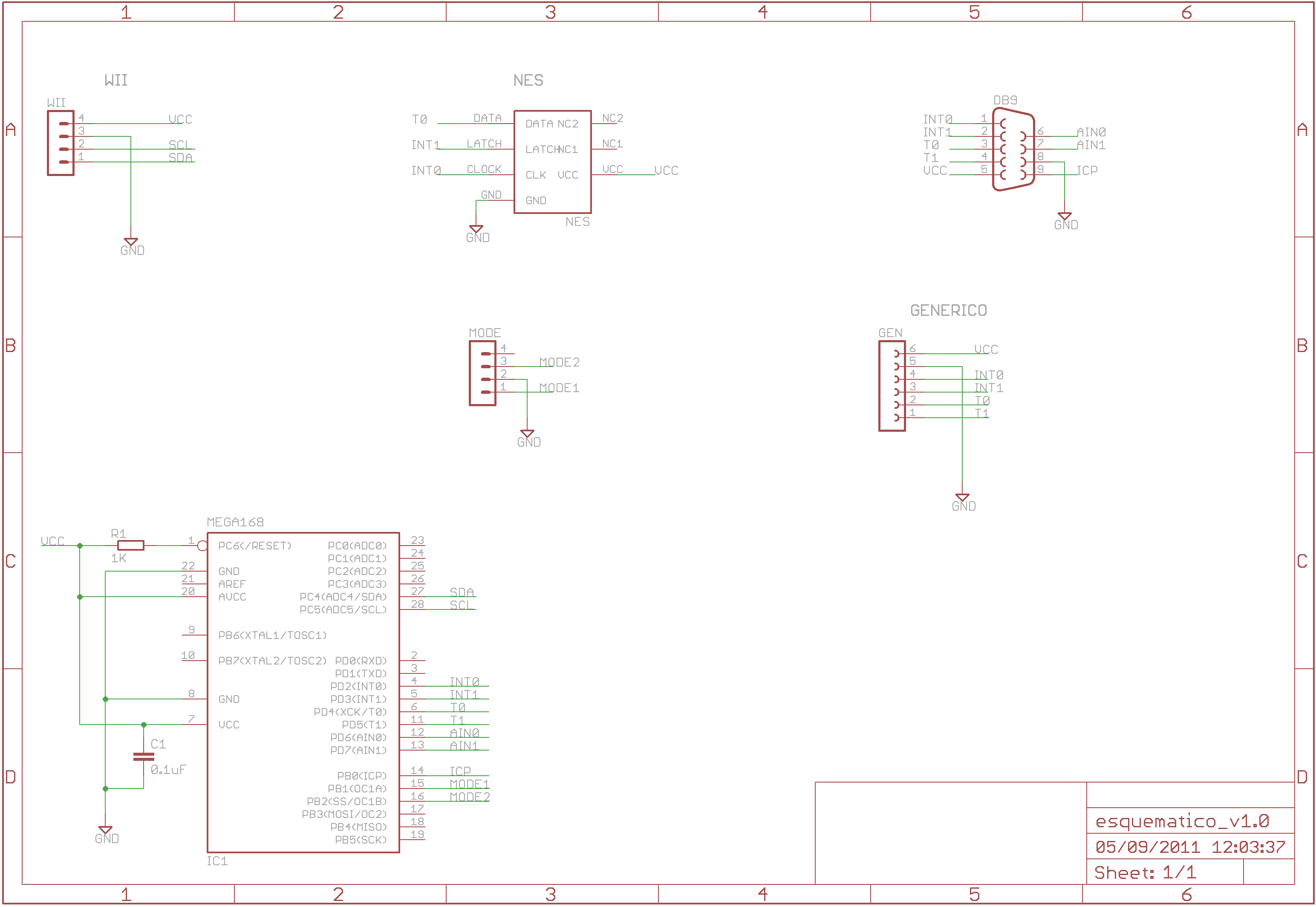
The Wii RetroPad Adapter allows the use of PlayStation 2, Genesis, NES, and SNES controllers with the Wii console. The Wii RetroPad Adapter is a versatile accessory designed to enhance the gaming experience by enabling compatibility between multiple classic gaming...
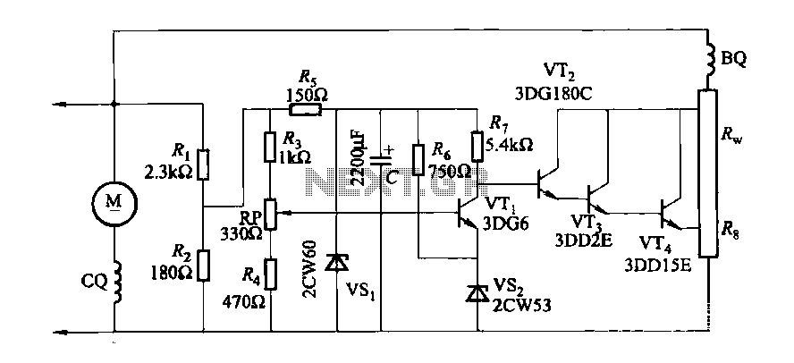
The DC generator automatic voltage regulator circuit is illustrated in Figure 7-53. This circuit is designed for a 40kW, 230V DC shunt complex machine, with a voltage change rate of up to 2.5 percent. In Figure 7-53, BQ represents...
This circuit utilizes a controlled half-plus fixed half-wave phase control method to regulate an 860-watt lamp load, allowing for power adjustment from half to full capacity. The circuit controls the light output of the lamp, enabling a range from...
The 555 IC is wired as an astable and the frequency is constant and independent of the duty cycle, as the total resistance (R charge + R discharge, notice the diode) is constant and equal to 22Kohm (giving a...
The project originated from a request by Tony Bowler, a member of the Long Eaton Club, who sought assistance in converting a "Golden Oldie" model to electric free-flight. He selected Vic Smeed's "Debutante" to be powered by seven AE...
Warning: include(partials/cookie-banner.php): Failed to open stream: Permission denied in /var/www/html/nextgr/view-circuit.php on line 713
Warning: include(): Failed opening 'partials/cookie-banner.php' for inclusion (include_path='.:/usr/share/php') in /var/www/html/nextgr/view-circuit.php on line 713