
The Hall A Wire-chamber Gas System Ops Manual
The gas supply system for the Hall-A spectrometers is designed with safety and efficiency in mind, ensuring that potentially flammable gases are handled properly. The mixing system plays a crucial role in maintaining the correct gas ratios essential for the operation of the VDC and FPP systems. The integration of safety features such as Excess Flow Valves and overpressure relief valves is paramount, as they provide critical protection against hazardous conditions that could arise due to gas leaks or pressure fluctuations.
The use of high-pressure gas bottles necessitates robust monitoring and control systems. The Matheson model 8590 controllers ensure that the gas supply is managed seamlessly, with real-time pressure monitoring allowing for immediate response to any changes in gas bottle status. The inclusion of mechanical pressure gauges provides an additional layer of safety, allowing operators to visually verify the pressure levels before proceeding with operations.
The solenoid valves, being normally closed, enhance safety by ensuring that gas flow is only permitted when all interlock conditions are satisfied. This design minimizes the risk of accidental gas release, which is particularly important in environments where flammable gases are utilized. The manual "Low Pressure Override" feature allows for controlled initial gas flow, while the automatic re-arming of the system ensures that operators are alerted to any potential issues with gas pressure.
Overall, the gas supply and mixing system for the Hall-A spectrometers is a sophisticated assembly that prioritizes safety, reliability, and operational efficiency. The detailed design and implementation of each component reflect the critical nature of the applications involved and the need for stringent adherence to safety regulations.Two detector systems in the Hall-A spectrometers make use of potentially flammable gasses: the Vertical Drift Chambers (VDC) and the Focal Plane Polarimeter (FPP) straw tubes. This document is intended to address the practical need for a users manual for this gas supply system as well as the formal requirement for a written operating procedure.
Th e reader specifically interested in safety systems and compliance with safety regulations is referred to the sections Overview, Interlocks, Checklist, Interlock System, Calculation of Hazard Class, Refrigerator Safety, and Call List. As of this writing both detector systems (FPP and VDC) are using a mixture of Argon and Ethane in roughly equal proportions, plus about 1% ethanol.
The Argon and Ethane are supplied from high-pressure gas bottles. They are combined in the desired proportion by a mixing system and this mixture is passed through a bath of ethyl alcohol which is maintained at a fixed temperature. See Figure 2. 3-1 for a schematic diagram of the gas supply / mixing system. The gas mixture is delivered to gas distribution racks in the Hadron Spectrometer and the Electron Spectrometer.
The transmission lines and the distribution plumbing have been designed as if the FPPs and VDCs were actually independent systems using different gas mixtures. This design was chosen in order to ease the expected transition to such a system in the future. Also supplied is a source of purge gas, currently pure argon. The distribution racks provide, for each detector, selection of either operating gas or purge gas, flow control and metering, overpressure relief to protect the detector components, exhaust flow measurement, and backflow prevention.
The bulk gas supply consists of two bottles each of Argon and Ethane. Except for fittings which vary by type of gas the two supplies have identical plumbing. One of the bottles for each gas is connected to the gas shed supply at all times by the Matheson model 8590 controllers inside the Hall A Gas Shed. The pressure in each bottle is sensed by a pressure switch whose signal is used by the Matheson model 8590 controller to change from an empty cylinder to a full cylinder.
The pressure of each bottle is also indicated locally by a mechanical pressure gauge on each flex hose. A pressure regulator for each type of gas reduces the pressure to approximately 45 psig. This is the pressure at which gas is supplied to the gas shed. It may be monitored by the outlet pressure gauges (PG-022, -023) on the pressure regulators and, inside the gas shed, on gauges PG-132, -133.
Prior to entering the shed the gas passes through manual valves (MV-032, -033), Excess Flow Valves (XF-042, -043), and Solenoid Valves (AV-052, -053). The Excess Flow Valves automatically close if the flow rate exceeds about 4 slpm at 45 psig. These valves must be manually reset after they trip. Refer to the section. Resetting a closed Excess Flow Valve for this procedure. The solenoid valves are electrically operated (24 VDC) normally-closed valves. Power must be supplied to the solenoids in order for gas to flow. Valve power is supplied, when interlock conditions are satisfied, by the Gas Interlock System. Note that one of the required interlock conditions is that there be ample gas pressure downstream of the solenoid valves.
System operators must use the manual "Low Pressure Override" pushbutton on the interlock panel (in the mixing room) in order to initially bring up the 45 psig supply pressure. The pushbutton circuit automatically re-arms after ample pressure is detected by the pressure switches (PS-112, -113).
These switches are located immediately above gauges PG-132 and -133. Just below these gauges are overpressure relief valves (RV -122, -123) which have been set to release if the supply pressure exceeds about 60 psig. After passing through check valves which prevent backstreaming the three gas supplies enter the mixing syst
🔗 External reference
Related Circuits
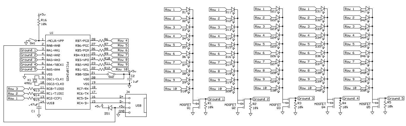
To control 40 LEDs using a single PIC 18F2455 microcontroller, the LEDs were organized into a configuration of four columns, each containing 10 rows of LEDs. Each LED in a column was connected to a separate pin on the...
The intersection of industry and data collection systems includes hydrometeorological control systems, robot control systems, and digital image transmission systems. This is facilitated by the electron transport of data information. The data transmission system is a crucial component of...
The Lorenz system is one of the few standard oscillators commonly used to explore chaos. An accessible description of its mathematical features and chaotic dynamics is presented by Thompson and Stewart. This important system was originally developed as a...
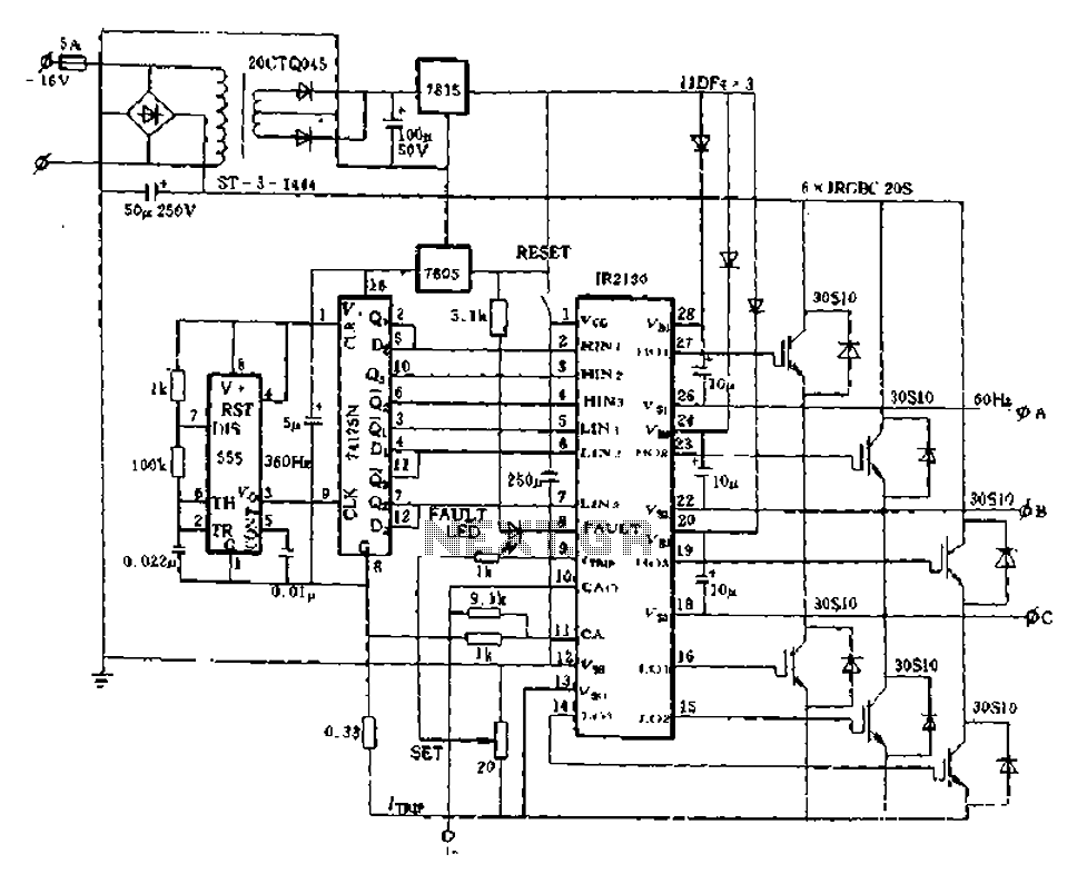
The application of the aforementioned advantages allows the IR2130 to be effectively utilized for DC cut crossing speed, DC servo systems, three-phase power inverters, and switching power supplies. Additionally, it is applicable in inverter power supplies, uninterruptible power supplies...
Manual stabilizers remain popular due to their straightforward construction, affordability, and high reliability, as they do not incorporate any relays. Manual stabilizers are widely utilized in various electronic applications, primarily due to their effective voltage regulation capabilities. These devices function...
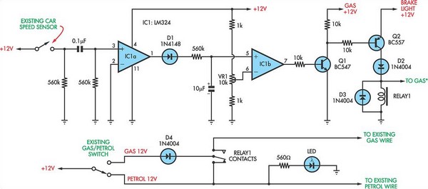
The following circuit illustrates a petrol gas switch sensor circuit diagram designed for a Pajero vehicle. It features a simple configuration utilizing the LM334 integrated circuit and operates automatically. The petrol gas switch sensor circuit is designed to monitor and...