
Under-Over-Voltage Beep for Manual Stabiliser
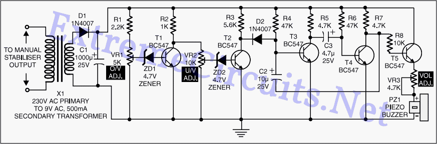
Manual stabilizers are widely utilized in various electronic applications, primarily due to their effective voltage regulation capabilities. These devices function by adjusting the output voltage to maintain a consistent level despite fluctuations in the input voltage. The simplicity of their design often includes a transformer, rectifier, and filter circuit, which work together to stabilize the output.
The absence of relays in manual stabilizers contributes significantly to their reliability and longevity. Without mechanical components, the risk of failure from wear and tear is minimized, making them suitable for environments where durability is essential.
In terms of construction, a typical manual stabilizer may consist of a step-down transformer that reduces the high voltage AC input to a lower level. The output from the transformer is then rectified using diodes, converting AC to DC. Following this, a filter capacitor smooths out the rectified voltage, providing a steady DC output.
Additionally, manual stabilizers often feature adjustable output settings, allowing users to select the desired voltage level. This adjustability is achieved through a potentiometer or variable resistor, enabling fine-tuning of the output voltage to meet specific requirements.
Overall, the combination of simple circuitry, cost-effectiveness, and robust performance makes manual stabilizers a preferred choice for many applications, including powering sensitive electronic devices and ensuring stable operation in varying electrical conditions.Manual stabilisers are still popular because of their simple construction, low cost, and high reliability due to the absence of any relays while covering.. 🔗 External reference
Related Circuits
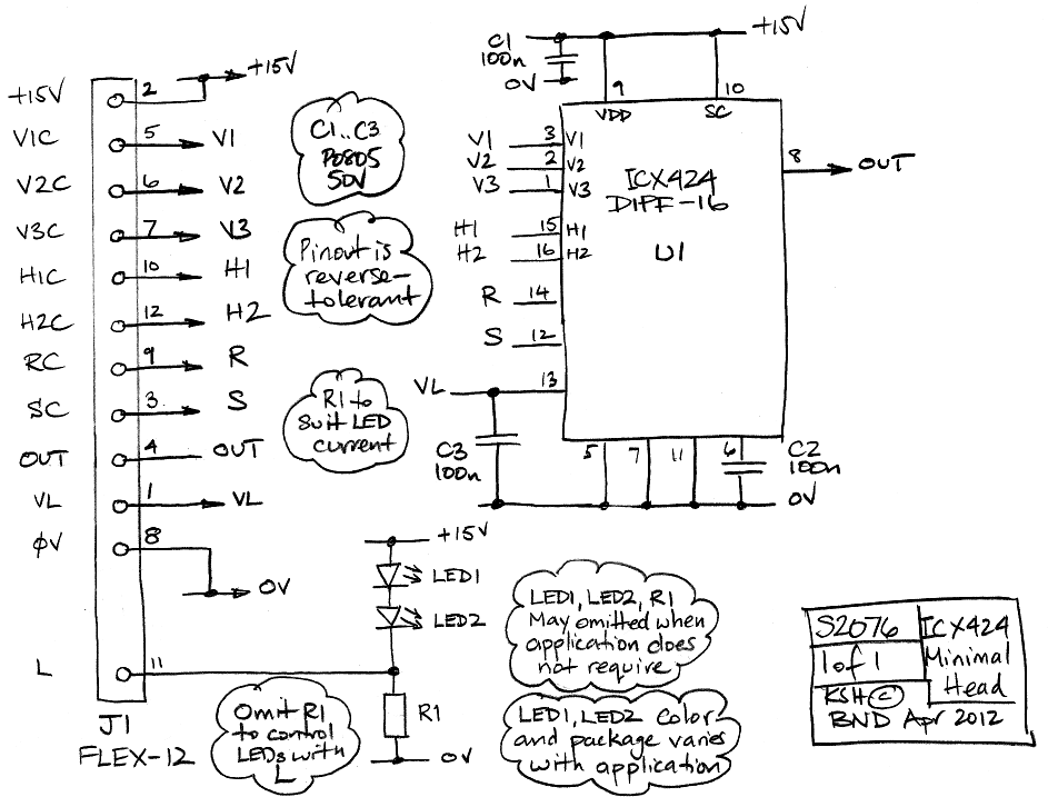
The ICX424 Minimal Head (A2075) features a single ICX424 image sensor and an optional pair of illumination LEDs. Power and drive signals enter the circuit board through a twelve-way flex connector. Three capacitors provide local decoupling of the supplies....
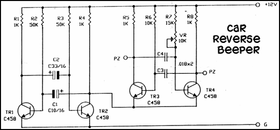
After installation in the car (not running but in reverse with the emergency brake engaged), the system functioned well. However, when the car was started and reversed out of the garage, the beeping frequency became erratic while tapping the...
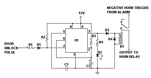
It is a significant advantage that most modern vehicles are equipped with built-in alarm systems. However, the sound of the horn when the alarm is armed can be perceived as noise pollution. Disconnecting the alarm system from the horn...
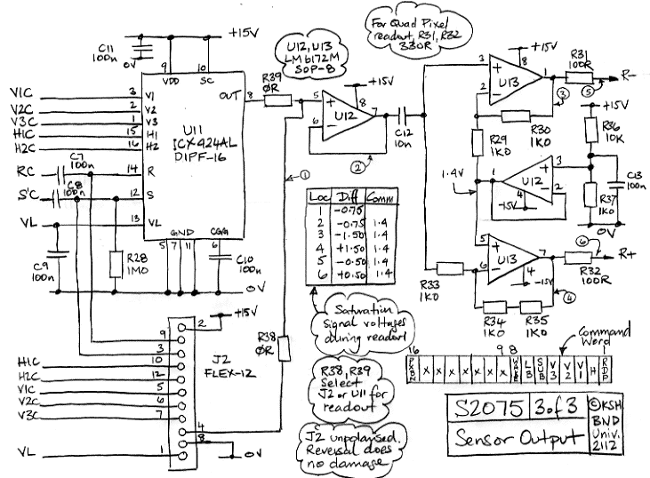
The Camera Head (A2075) is a LWDAQ device designed to control and read a single ICX424 image sensor. The circuit includes a socket for soldering a 16-pin sensor directly and features a 12-way flex socket for connecting an auxiliary...
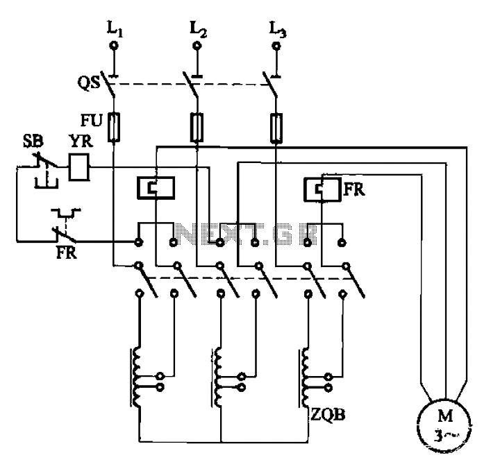
The circuit illustrated in Figure 3-47 involves a three-phase AC motor that is initially connected through a step-down autotransformer. To initiate operation, the power switch is closed, and the operating handle is pushed to the start position. Once the...
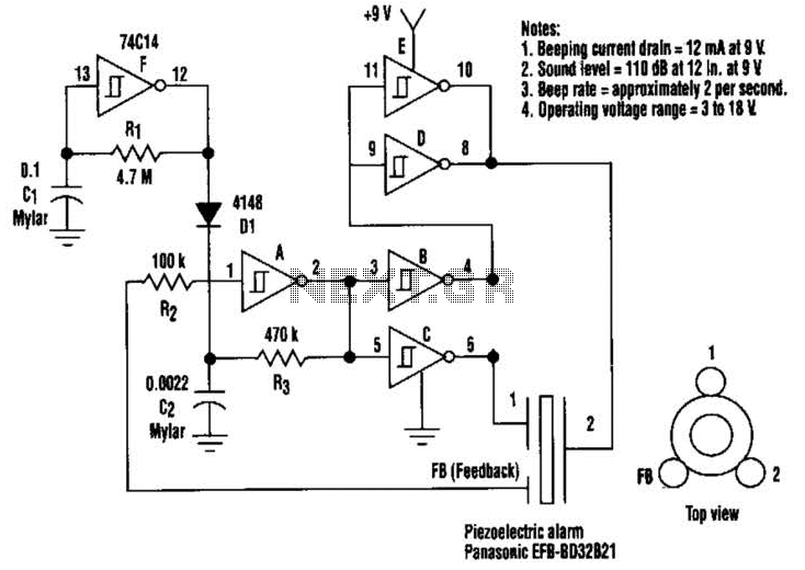
This circuit generates a loud sound of 110 dB using a 9 V power supply. It incorporates a single 74C14 (CD40106B) CMOS hex inverting Schmitt-trigger IC, which is utilized with a piezoelectric device that includes a feedback terminal. The...