
RC Receiver for model airplane
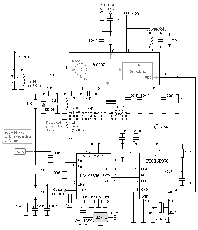
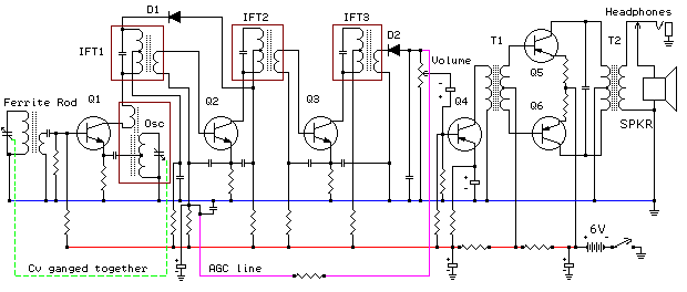
More: The receiver is built around the MC3371 FM receiver circuit. The oscillator is located at pins 1 and 2. A coil L2 in conjunction with a 15pF capacitor forms the oscillating unit. To vary the frequency, a varicap (BB139) is added. By changing the voltage across this varicap, its capacitance varies, which in turn alters the oscillating frequency. The oscillator functions as a Voltage Controlled Oscillator (VCO).
The first step in testing the oscillator is to disconnect the Vout from pin 2 of the PLL LMX2306 and connect it to ground. This configuration allows the oscillator to operate at its lowest frequency. Using a wireless frequency counter, it was determined that the oscillator initially operated at 33MHz. By slightly stretching the coil L2, the oscillation frequency was adjusted to 35MHz. When Vout was connected to +5V, the oscillator frequency increased to 36MHz. By varying the Vout from 0 to +5V, the oscillation frequency could be modulated between 35 and 36MHz. The Vtune was then reconnected to the PLL.
During testing, the PIC was programmed to set the frequency to 35.565 MHz, corresponding to Channel 71. Upon retesting, the PLL regulated the Vout voltage until the oscillator locked onto 35.565MHz. A DC meter indicated that Vout stabilized at 0.8V, confirming the oscillator's lock to the desired frequency.
The synthesizer circuit LMX2306 was incorporated to control the frequency. The PLL circuit includes a pickup coil connected to pin 6, positioned close to coil L2 to capture some oscillating energy. An external reference crystal of 12.8 MHz is utilized in the PLL circuit.
Pin 2 of the LMX2306 contains a PLL filter that generates the Vout, which serves as the regulating voltage for the VCO. The PLL continuously attempts to regulate Vout to ensure that the oscillator maintains the desired frequency. This desired frequency is stored in the PIC EEPROM and is loaded into the synthesizer (LMX2306) upon power-up. Instructions for programming the EEPROM for various frequencies will be provided.
At pin 14 of the synthesizer, a control output is available, which provides the reference frequency for testing. It is important to note that the output signal is not symmetrical, with positive pulses lasting only a few microseconds, making them difficult to observe on an oscilloscope. This issue can be resolved by connecting the output to a 74HC4020 14-stage binary counter, using pin 10 as the clock input. The output at Q0 (pin 9) will yield a symmetrical square wave at half the frequency, while Q1 (pin 7) will provide a frequency divided by four. Further details can be referenced in the respective datasheets.This project will explain how you can build a receiver for 35MHz. The receiver is based on the FM receiver circuit MC3371, and the frequency is PLL controlled with LMX2306 circuit. In this project I will build a radio receiver for RC air planes. There are 20 different frequencies (channels) used for radio controlling RC air planes. Each user needs it own frequency, else you will controll someone else plane. The lowest frequency is 35.010MHz and the highest is 35.200MHz. In practice there are 20 different crystalls for each channel. In my receiver I have no crystal for each frequency, instead I use a frequency synthesizer. With this system I can in a very simple way choose any channel I want to receive. I will explain how a frequency synthesizer works and how you can control it. The receiver is built around the circuit MC3371 FM receiver. The oscillator is located at pin 1 and 2. L2 with the 15pF makes an oscillating unit. To vary the frequency a varicap is added bb139. By changing the voltage over this varicap the capacitance will change and the oscillating frequency will also change. The oscillator is made to work as "Voltage Contolled Oscillator" VCO. The first thing you should test is that the oscillator is working. I disconnected the Vout from pin 2 of the PLL LMX2306. I then connected Vout to ground and check the oscillator. The oscillator should now oscillate at the lowest frequency. With my "Wireless frequency counter" I found that the oscillator was working at 33MHz. I streatched the coil L2 a bit until it oscillated at 35MHz. I then connected Vout to +5V and now the oscillator was oscillating at 36MHz. Great, as "Basil" would have said! By changing the Vout from 0 to +5V I could change the oscillating frequency from 35 to 36MHz. I then reconnected the Vtune to the PLL. In my test I had programmed the PIC to set the frequency at 35.565 MHz = Channel 71. When I tested the unit again the PLL tried to regulate the Vout voltage untill the oscillator locked to 35.565MHz.
I probed Vout with a DC meter and it stoped ad 0.8V and the frequency of the oscillator was now locked to the 35.565MHz. Great, great... To control the frequency a synthesizer circuit LMX 2306 has been added. The PLL circuit has a pickup coil to pin 6. This coil should be put close to the L2 coil for picking up some of the oscillating energy. The PLL circuit has an external reference crystal of 12.8 MHz. At pin 2 of MX2306 you will find a PLL filter to form the Vout which is the regulating voltage of the VCO.
The PLL try to regulate the Vout so the oscillator keeps the frequency loocked to desired frequency. The desired frequency is programmed into the PIC EEPROM and is clocked into the synthesizer (LMX2306) at power up. I will below explain how to program the EEPROM for different frequencies. At pin14 of the synthesizer you have a controll output. At this output you will find the reference frequency for testing. (I must warn you because the signal is not symetrical in shape. The positiv puls are only a few microsecond so you will have difficult to see it at oscilloscope.) I solved it by connecting it to a 74HC4020 14-stage Binary Counter to pin 10 Clock input.
At Q0 (pin 9) you will have a symetrical square wave with half frequency since the circuit is a counter. At Q1 pin 7 it will be divided by 4, see datasheets for more info. 🔗 External reference
Related Circuits
A new high-performance regenerative receiver is available as a kit. The inclusion of an innovative regenerative detector circuit enhances sensitivity and overall performance. The regenerative receiver kit is designed to provide users with a high-quality radio frequency (RF) reception experience....
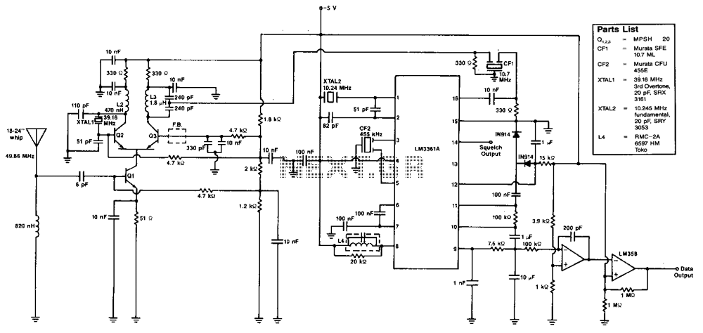
The various signal frequencies are obtained for an incoming carrier centered at 49.86 MHz. The receiver employs double conversion, with intermediate frequencies (i-fs) at 10.7 MHz and 455 kHz. Ceramic filters are used in both intermediate frequencies for selectivity...
This receiver is designed around the widely used ZN414 integrated circuit, which covers the medium wave band from approximately 550 to 1600 KHz. The coil and tuning capacitor can be salvaged from an old medium wave radio to expedite...
An AM receiver depends on the original carrier signal (station frequency) being amplitude modulated, meaning the original amplitude (strength) varies at an audio rate. Figure 1 illustrates an unmodulated carrier signal as it might appear on an oscilloscope, showing...
This document outlines the hardware modifications required to adapt a Kenwood TK-931 transceiver for 902 MHz repeater receive operation. It does not include the programming effort needed for the desired operating frequency, which can be performed using Kenwood KPG-5D...
Circuit schematics for the 555-based PLL laser light PFM receiver. Although R4 is shown as a resistor, it is advisable to replace it with a 10-kΩ precision potentiometer to allow for fine-tuning of the transmitter's center frequency. Experimentation with...