
The instrumentation amplifier
The instrumentation amplifier is a sophisticated circuit designed to amplify differential signals while rejecting common-mode noise. It typically employs three operational amplifiers: two op-amps configured as buffers (also known as voltage followers) and one op-amp for the differential amplification stage. The buffered stage ensures that the input signals are isolated from the resistive network, thereby maintaining high input impedance and preventing loading effects on the signal sources.
The three resistors in the circuit play a crucial role in defining the gain of the instrumentation amplifier. The resistor Rgain is the key component that allows for gain adjustment. By varying the resistance of Rgain, the gain of the entire amplifier can be adjusted without affecting the symmetry of the circuit. The gain can be expressed as:
\[ \text{Gain} = 1 + \frac{2R}{R_{gain}} \]
where R represents the value of the resistors connecting the buffer stages. This equation illustrates that the gain can be increased by decreasing the value of Rgain, which in turn increases the differential amplification of the input signals.
The high input impedance of the instrumentation amplifier makes it ideal for applications where the signal source must not be loaded down, such as in sensor applications (e.g., thermocouples, strain gauges). The design also minimizes errors due to voltage drops across the input connections, enhancing measurement accuracy.
In summary, the instrumentation amplifier is a versatile and effective solution for applications requiring precise differential signal amplification with a simple means of gain adjustment. Its architecture, featuring high input impedance and the ability to alter gain through a single resistor, makes it a preferred choice in many electronic measurement and data acquisition systems.As suggested before, it is beneficial to be able to adjust the gain of the amplifier circuit without having to change more than one resistor value, as is necessary with the previous design of differential amplifier. The so-called instrumentation builds on the last version of differential amplifier to give us that capability: This intimidating circ
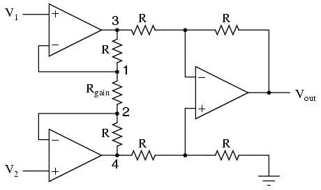
uit is constructed from a buffered differential amplifier stage with three new resistors linking the two buffer circuits together. Consider all resistors to be of equal value except for Rgain. The negative feedback of the upper-left op-amp causes the voltage at point 1 (top of Rgain) to be equal to V1.
Likewise, the voltage at point 2 (bottom of Rgain) is held to a value equal to V2. This establishes a voltage drop across Rgain equal to the voltage difference between V1 and V2. That voltage drop causes a current through Rgain, and since the feedback loops of the two input op-amps draw no current, that same amount of current through Rgain must be going through the two "R" resistors above and below it. This produces a voltage drop between points 3 and 4 equal to: The regular differential amplifier on the right-hand side of the circuit then takes this voltage drop between points 3 and 4, and amplifies it by a gain of 1 (assuming again that all "R" resistors are of equal value).
Though this looks like a cumbersome way to build a differential amplifier, it has the distinct advantages of possessing extremely high input impedances on the V1 and V2 inputs (because they connect straight into the noninverting inputs of their respective op-amps), and adjustable gain that can be set by a single resistor. Manipulating the above formula a bit, we have a general expression for overall voltage gain in the instrumentation amplifier: Though it may not be obvious by looking at the schematic, we can change the differential gain of the instrumentation amplifier simply by changing the value of one resistor: Rgain.
Yes, we could still change the overall gain by changing the values of some of the other resistors, but this would necessitate balanced resistor value changes for the circuit to remain symmetrical. Please note that the lowest gain possible with the above circuit is obtained with Rgain completely open (infinite resistance), and that gain value is 1.
An instrumentation amplifier is a differential op-amp circuit providing high input impedances with ease of gain adjustment through the variation of a single resistor. 🔗 External reference
Related Circuits
The basis for this amplifier has been around now for several years as Project 3A, and requires only relatively small modifications to be able to operate in Class-A. The biggest change is in output power (reduced dramatically from the 60-100W...
Currently, a basic MOSFET amplifier or power amplifier is designed to deliver an output power of ±100 Watts RMS with an 8 Ohm load, or ±160 Watts RMS with a 4 Ohm load. The simplicity of this circuit results...
This is a circuit that ensures that you can connect two amplifiers together so you get more power. When called in bridge linking two amplifiers plus you can link the outputs of the amplifiers to the speaker. One of...
In all instances where Darlington transistors serve as output devices, it is crucial for the sensing transistor (Q4) to maintain close thermal contact with the output transistors. Consequently, a TO126-case transistor type was selected for ease of mounting onto...
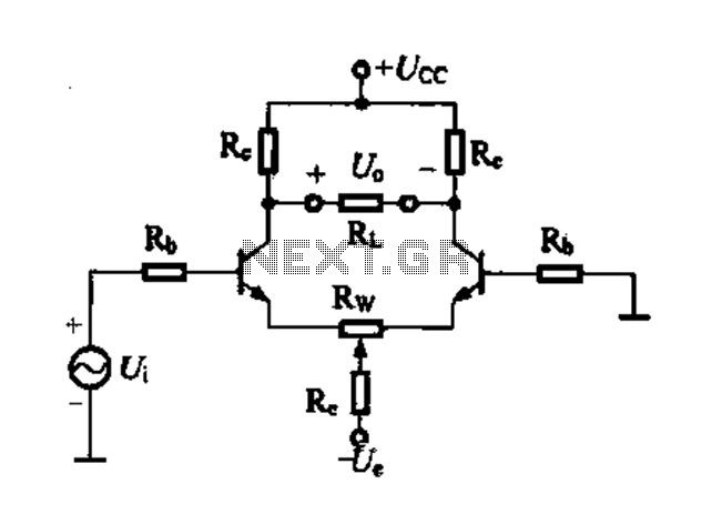
Differential amplifier circuit with four connection methods and characteristics for comparison. The circuit exhibits magnification with a single tube when symmetrical. Additionally, CMRR (Common Mode Rejection Ratio) is adapted from single-ended input to a double-ended output. The differential amplifier is...
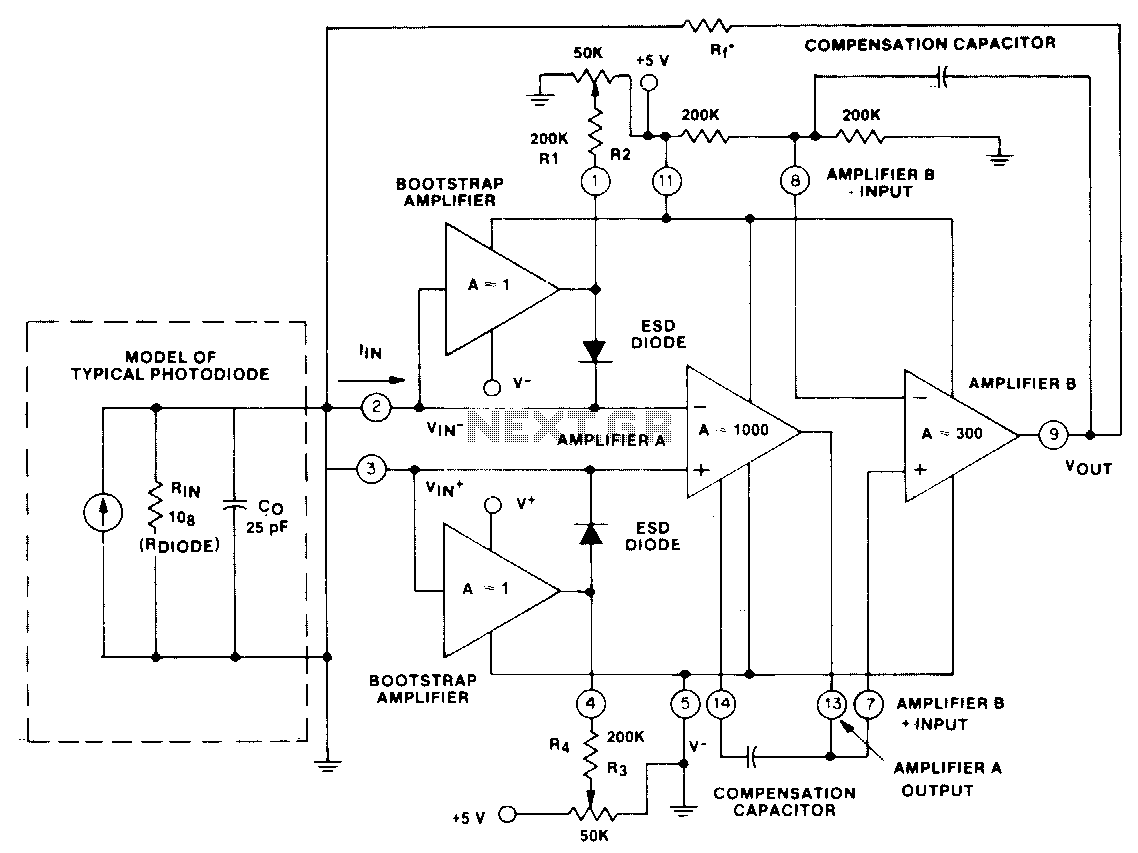
This circuit utilizes a CA5422 dual BiMOS microprocessor operational amplifier. The bootstrap amplifiers reduce bias currents while providing electrostatic discharge protection. Additionally, the potentiometers and their corresponding resistors, R1 through R4, allow the user to adjust bias currents to...
Warning: include(partials/cookie-banner.php): Failed to open stream: Permission denied in /var/www/html/nextgr/view-circuit.php on line 713
Warning: include(): Failed opening 'partials/cookie-banner.php' for inclusion (include_path='.:/usr/share/php') in /var/www/html/nextgr/view-circuit.php on line 713