
The LC oscillator circuit for electronic cello

The improved Hartley oscillator operates based on the principle of feedback and utilizes an inductor-capacitor (LC) tank circuit to generate oscillations. The configuration typically consists of two inductors and a capacitor, which together determine the oscillation frequency. The frequency of the output signal can be finely tuned by varying the base current through a transistor, which acts as the active component in the oscillator circuit.
In this circuit, the inductors are connected in a specific manner to create a tapped inductor configuration, which provides the necessary phase shift for sustained oscillations. The capacitor is connected across the inductor to form the resonant tank circuit. The resonant frequency (f) of the oscillator can be calculated using the formula:
f = 1 / (2π√(L_total * C))
where L_total is the equivalent inductance of the combined inductors and C is the capacitance. By adjusting the base current, the operating point of the transistor can be modified, which in turn affects the gain and oscillation conditions, allowing for frequency modulation.
The output of the oscillator is characterized by a peak amplitude greater than 6V when a load resistance of 6kΩ is applied, indicating a robust output suitable for driving other electronic components. This feature is particularly beneficial in applications such as electronic cello circuits, where a stable and adjustable frequency is required to produce desired sound characteristics.
Overall, the improved Hartley oscillator circuit exemplifies a versatile design that can be effectively implemented in various electronic applications, especially in musical instrument circuitry, due to its ability to deliver high output amplitudes and adjustable frequencies.This circuit is the improved hartley oscillator circuit, changing the base current can adjust the frequency in a given range. The output signal amplitude is higher than 6V in 6k? load resistance,and it is suitable for electronic cello circuits.. 🔗 External reference
Related Circuits

A dimming control circuit generates a dimming control signal to determine the brightness of at least one light-emitting diode. The dimming control signal consists of multiple bright-dark cycles, each comprising a bright phase and a dark phase. The bright...
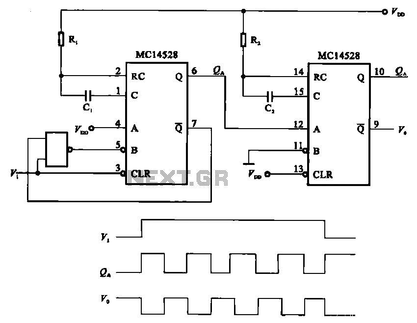
The pulse generating circuit monitors signals using monostable flip-flops. It generates a single-shot output signal based on the input pulse signal. A key signal from the monostable flip-flops is represented in a formula, with the input (V1) and output...
This circuit deactivates an amplifier or any connected device when a low-level audio signal at its input is absent for at least 15 minutes. By pressing P1, the device is powered on, supplying power to any appliance connected to...
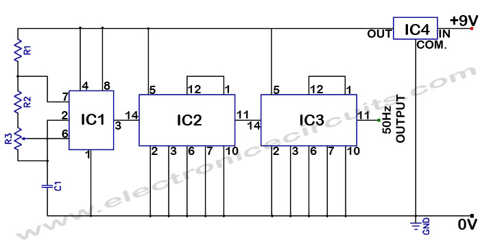
Accurate 50Hz Oscillator Circuit Using 555 and 7490. This circuit generates a 50Hz pulse. It consists of a 555 timer and two 7490 divide-by-ten counters. The circuit utilizes a 555 timer configured in astable mode to produce a square wave...
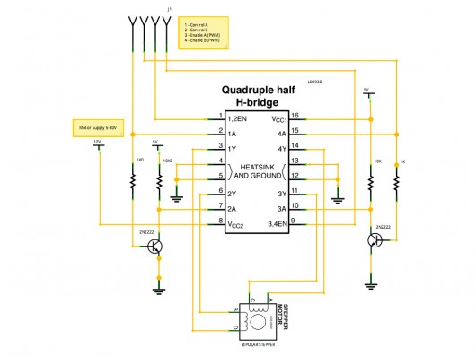
A stepper motor controller based on schematics available on the Arduino website. Initially, a two-pin configuration was attempted for a bipolar stepper motor, but it did not function as expected, especially with the library provided on the site. The...
Project Manager Jim Heck, G3WGM, has provided an exclusive audio interview to Bob McCreadie, G0FGX, from TX Factor, detailing the tests and potential issues involved. Membership in AMSAT-UK is available to anyone interested in amateur radio satellites or space...