
10 led simple roulette wheel circuit

The circuit design for the 10 LED roulette wheel utilizes a microcontroller or a simple timer integrated circuit to control the sequencing of the LEDs. The core of the circuit comprises ten LEDs arranged in a circular pattern, each connected to a digital output pin of the microcontroller. A push-button switch serves as the input mechanism to start the LED sequence.
Upon pressing the button, the microcontroller activates a timer that dictates the speed of the LED sequence. Initially, the LEDs light up in rapid succession, creating the illusion of spinning. The timing algorithm implemented in the microcontroller gradually increases the interval between each LED activation, simulating a deceleration effect. This is achieved through a loop that adjusts the delay based on a predefined decrementing time variable.
The randomness of the final LED illuminated is determined by the duration the button is held down. A longer press results in a longer delay before the sequence stops, while a shorter press leads to a quicker halt. This feature can be implemented by measuring the time the button is pressed using an analog input or a timer interrupt. The microcontroller reads this duration and uses it to select a final LED position based on a calculated random index.
To enhance the foolproof nature of the roulette application, the circuit can incorporate debouncing logic for the push-button to prevent false triggering due to mechanical bounce. Additionally, the circuit can include a reset function to allow users to restart the sequence at any time.
Overall, this simple yet effective circuit design provides an engaging interactive experience, combining basic electronic components and programming techniques to create a functional roulette wheel simulation.A very simple 10 LED roulette wheel circuit is shown here. pressing the button starts the LEDs in a rotational motion (sequencing) at full swing initially, and gradually slows down, until it stops to a particular, randomly selected LED. The randomness of the selection depends upon the time for which the push remains switched ON by the finger.
Even a difference of 0. 1 second is able to change the position of the final LED position, making the rouletteapplicationhighly foolproof. 🔗 External reference
Related Circuits

The pitch of the tone is determined by the resistance being tested. The tester can respond to resistances in the hundreds of kilohms range, while also being capable of distinguishing differences as small as tens of ohms in low-resistance...

The Hitachi NP8C switching power supply circuit is illustrated in FIG. The Hitachi NP8C power models include CTP236, CEP320D, CRP350D, 450D, Furi HFC-236, 450, and Venus C37-401, C46-1, C563, among others. This circuit was widely used in early Chinese...
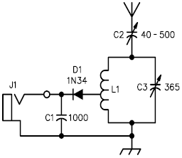
A crystal radio receiver is a very simple radio receiver that requires no battery or external power source, operating solely on the energy harvested from radio waves through a long antenna. A crystal radio receiver is a passive radio receiver...
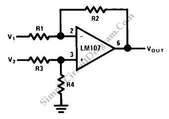
This circuit is a difference amplifier. It functions as an inverting amplifier that enables the subtraction of two voltages, effectively performing a summation. The difference amplifier is a fundamental circuit configuration in analog electronics, primarily used for amplifying the difference...
This circuit generates dual-tone bell ringing similar to most doorbell units. It can be used in various applications beyond just doorbells. Several options will be provided in the notes to accommodate different needs. The circuit, as depicted in the...
This tester is designed for tracing wiring on Printed Circuit Boards (PCBs). Resistors below 50 ohms function as a short circuit, while those above 100 ohms behave as an open circuit. The circuit utilizes a simple multivibrator activated by...