
The Link 4+0 ?– Internal Intercoms

The intercom circuit utilizes a straightforward architecture that integrates several essential components for effective communication. The DTMF decoder (IC2) plays a critical role in interpreting the input signals from the keypad, translating them into binary outputs for further processing. The 1 x 16 decoder (IC3) is pivotal in managing the routing of calls to the appropriate line relays (LR1 to LR4), ensuring that each handset can connect to the intended party. The driver transistor (Q5) amplifies the control signals, enabling the line relays to engage properly and facilitate the communication link.
The Ring Trip Circuit (RTC), incorporating flip-flop FF1, is designed to manage the ringing signal and ensure that it is only active when necessary. The phototransistor in the collector of OC1 serves as a feedback mechanism, allowing the system to reset after a call is completed. This design minimizes the risk of false triggering and enhances the reliability of the intercom system.
The inclusion of additional features, such as the ability to silence the ringer with the # key, adds significant user convenience, making the intercom system more versatile. The potential for repurposing unused outputs from IC3 for other applications further enhances the overall functionality of the system, allowing users to integrate it into various environments seamlessly. This intercom design exemplifies a practical solution for communication needs in settings where external phone lines are not viable.This version of the Link is for those who really need a good cheap intercom that will work reliably, but without access to an outside Telco line. This could be in a pre school, a hobby farm or a small workshop or factory, where external phone traffic needs to be kept separate and protected from phone abusers and kids playing around … It follows ma
inly the principals of the Link pulse dial circuit, but with the modifications and additions of the Link A2B+1 for DTMF dialing. Basically what I ’ve done is remove the OSL relay and the flip flop (FF2) that controlled its activation and release, and added an extra two internal handsets and their associated relays and components.
FF1 (as part of the Ring Trip Circuit or RTC) is still there, but is now shown down the bottom of the diagram for simplicity ’s sake. Internal wiring for the RTR relay is as per the Link A2B circuit. When any phone is picked up off hook and a number from 1 to 4 on the keypad is pressed, the DTMF decoder chip (IC2) decodes this into IC3 (1 x 16 decoder) and the output of IC3 is then fed to the appropriate base resistor of Q1 to Q4 (R11 through R14).
Pin 11 of IC3 goes low, removing the high from pins 12 and 8 of IC1 and impulsing of the selected line relay (LR1 to LR4) begins, via driver transistor Q5 and the appropriate buffer transistor (Q1 to Q4). When the called party answers the call, the RTC circuit ‘trips ’ the ring current, impulsing along with the ring tone is halted, and the conversation can proceed.
When the conversation is completed and both phones are hung up, the collector of OC1 ’s phototransistor goes high and resets both FF1 and IC3. Pin 11 of IC3 goes high again, halting the impulsing action of IC1 but providing dial tone from pin 5 in the reset state, ready for the next call.
One extra nifty little feature involves the # output (pin 14 of IC3). If you connect this to the set (S) input of FF1, you can halt the ringer if someone calls your extension while you ’re away. You can pick up another extension anywhere else and press the # key and effectively ‘pick up ’ the call.
This feature prevents the other phone from continuing to ring and also halts the ring tone from overpowering your conversation. In principal, it follows very closely the features of the Link pulse dialing version, except that there ’s only a two wire circuit between each handset and the ‘black box ’ switcher.
In reality, tone dialing is more efficient, and you could easily use some of the other unused outputs of IC3 for remote control purposes (turning on sprinklers or low voltage garden lights, door entry systems etc. ) 🔗 External reference
Related Circuits
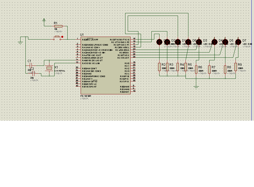
The code in mikroC PRO for the PIC16F887 microcontroller is designed to operate with an 8.000 MHz clock frequency on a Microchip 44-pin demo board. The routines have been developed using HITECH C, but the focus is on utilizing...
The author described assembling this circuit on a 1"*1" perf board, I actually laid out a small PC board with excellent results. In this era of surface mount components, I think a much smaller version can be laid out...
This LED series will blink alternately. The operation is determined by the NE555 integrated circuit, with transistors used to reinforce each section (20 upper, 20 lower) for optimal performance. The 555 circuit described below functions as a flashing bicycle...
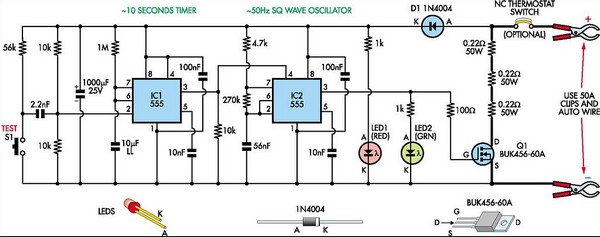
This circuit is designed to assess the condition of lead-acid and gel cell batteries with capacities exceeding 20Ah. It switches a load of approximately 18A at a frequency close to 50Hz, allowing for the measurement of the battery's internal...
The fundamental theory behind infrared technology necessary for this tutorial was previously covered in the Infrared Receiver tutorial, so a concise overview will be provided here. The explanation will begin with a general description of infrared and its relevance...
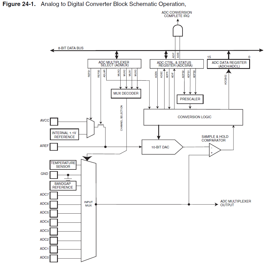
When using the internal 1.1V reference for the ADC, if the analog input exceeds 1.1V, such as 2.5V, it will not harm the microcontroller. Instead, the ADC value will clip at 0x3FF. Based on practical experience, it has been...