
internal resistance tester for
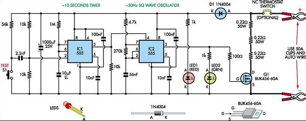
The circuit operates effectively by utilizing two 555 timer ICs to control the timing and switching of the load, which is essential for measuring the internal resistance of lead-acid and gel cell batteries. The monostable configuration of IC1 ensures that the test duration is precisely controlled at 10 seconds, providing a stable period for the measurement process. The astable configuration of IC2 generates a square wave signal at approximately 50Hz, which is necessary for the load switching.
The power MOSFET (Q1) serves as a high-efficiency switch capable of handling the 18A load without significant power loss. The inclusion of three 0.22Ω 50W resistors in series allows for the proper calibration of the load, ensuring that the circuit can effectively simulate the conditions under which the internal resistance is measured.
LED indicators (LED1 and LED2) provide visual feedback to the user, enhancing usability. The optional thermostat adds a layer of protection against potential overheating, ensuring the longevity and reliability of the circuit during repeated use.
To ensure accurate measurements, the procedure emphasizes the importance of checking the battery's state before conducting tests. This includes verifying the electrolyte level and ensuring the battery is adequately charged. The guidance to measure the voltage drop across the terminals while the headlights are on aids in identifying any potential issues with the battery connections, which could affect the accuracy of the internal resistance measurement.
Overall, this circuit design provides a reliable and straightforward method for assessing the health of lead-acid and gel cell batteries, making it a valuable tool for maintenance and diagnostics in automotive and other applications.This circuit is designed to check the condition of lead-acid and gel cell batteries with capacities greater than 20Ah. It switches a load of about 18A at a rate close to 50Hz so that the internal resistance of the battery can be measured using a digital multimeter across the battery terminals.
The measured AC voltage in millivolts divided by 10 (i e, a shift of the decimal point) is approximately equal to the battery`s internal resistance in milliohms. As shown, the circuit is quite straightforward and is based on two 555 timer ICs (IC1 & IC2) and power Mosfet Q1.
IC1 operates as a monostable timer with a period of 10s. When switch S1 (Test) is pressed, IC1`s pin 3 output goes high for 10s and this enables IC2 which operates as a 50Hz astable oscillator. IC2 in turn drives power Mosfet Q1 which is connected across the load in series with three 0. 22W 50W resistors. IC2 then turns off again after 10s - ie, at the end of the monostable timing period. LED1 provides power indication when the circuit is connected to a battery, while LED2 (green) comes on during the test period.
The thermostat is not necessary unless the unit is to be used repeatedly (the Jaycar ST-3823 70 °C unit is suitable) and you want to protect the output circuit against overheating. The power Mosfet does not need cooling but the thermostat and the 0. 22W 50W resistors should all be mounted on an aluminium heatsink at least 2mm thick. In practice, the internal resistance of car batteries can vary from about 15mW down to about 3mW. Before testing the battery, check that the electrolyte level is correct and that the voltage across its posts exceeds 12.
5V for a nominal 12V battery; ie, close to full charge. That done, switch on the car`s headlights and measure the DC voltage between each battery post and its connecting terminal. It should be less than 10mV in both cases; if not, the terminals need cleaning. Once you`ve done that, you can turn off the headlights, connect the tester and proceed with the internal resistance test.
Be sure to connect the multimeter`s test probes directly to the battery posts, to read the internal resistance (not the battery terminals). 🔗 External reference
Related Circuits
While developing an infrared (IR) extender circuit, a method was required to measure the relative intensities of different infrared light sources. This circuit is the culmination of that research. It utilizes a photodiode, specifically the SFH2030, as the infrared...
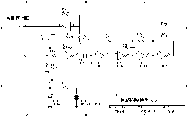
Continuity tester to check continuity in the circuit (Insakittochekka) is. The continuity check over the circuit board wiring that can be checked at a lower voltage semiconductors do not conduct contained in the circuit, you can just check the...
The Eico 666 is a capable tube tester whose functionality can be expanded with a modest investment of time to understand its schematic, operational regimes, and methods for adding new functionalities. This tester is known for supplying sufficient voltages...
A program is available to control a simple servo motor in both directions. This program has been tested and can be shared for others to benefit from it. It allows the servo motor to rotate in both clockwise and...
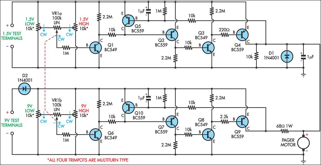
Many blind and deaf-blind individuals utilize portable electronic devices to aid their daily activities; however, they face challenges when testing the batteries used in these devices. While talking voltmeters exist, there is no equivalent device suitable for deaf-blind users....
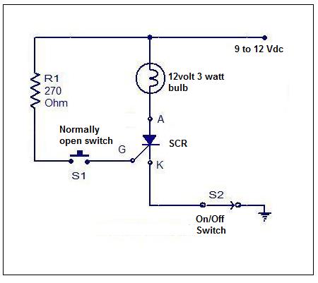
Although SCRs and TRIACs are not present in all electronic equipment, they are significant components. Understanding how to test them is essential for troubleshooting. Testing these components can be done with meters, but using an SCR/TRIAC tester is generally...