
The same capacitance parameters easy to change the cutoff frequency of the low pass filter 24dB-oct

A 24 dB/octave Butterworth filter is a well-known design in analog signal processing, characterized by its maximally flat frequency response in the passband. This particular design employs two cascaded filters, each contributing a 12 dB/octave slope, resulting in a total of 24 dB/octave. The filters are designed to ensure a smooth transition between the passband and the stopband, minimizing ripple and phase distortion.
The 3 dB cutoff frequency is a critical parameter in filter design, marking the frequency at which the output power drops to half of its maximum value. In this case, the cutoff frequency can be fine-tuned through the adjustments made to the gain settings, which are normalized to two units in the soil context. The adjustments of 0.541 and 1.306 for the first and second stages, respectively, are essential for optimizing the filter's performance and achieving the desired frequency response.
The feedback mechanism in the circuit is vital for stabilizing the filter's response. The feedback resistors are calculated based on the specified parameters, with R1 set at 2 kΩ and R2 at 12.35 kΩ. These resistors help define the gain of the filter, ensuring that the output signal remains within the desired amplitude range while maintaining the filter's characteristic response.
Additionally, the connection to ground through a Phoenix connector ensures reliable performance and easy integration into larger systems. The calculated feedback path, as indicated, plays a crucial role in determining the overall behavior of the filter, particularly in managing the gain and stability of the output signal.
Overall, this filter design is suitable for applications requiring precise frequency selection and signal integrity, making it a valuable component in various electronic systems, including audio processing, communications, and instrumentation. The careful selection of component values and the attention to gain adjustments contribute to the robustness and effectiveness of the filter in practical applications.24dB/oc seven times Butterworth (maximally flat characteristic) constituted by the two filters, each box has two books enough filter (12dB/oct), in order to make a 3dB point tw o units into soil cutoff frequency normalized, must first and second mouth enough baskets at sub-cut adjustment thistle 0.541 and 1.306 fold to take the gain to improve port by value according to A. 3 a (l/mouth.) (Taboo for the series 1, 2) calculate the required gain.. Jic resistance path to ground is fed Phoenix iok0 time, cut off the feet according to B. (A.-1) x IO 10I calculate the feedback resistor hall., Library lI, R. 1. S2k mouth, R1. 12.35 ka Since the filter with passband gain, so the input stage 4. Attenuation of 1/2. 53.
Related Circuits
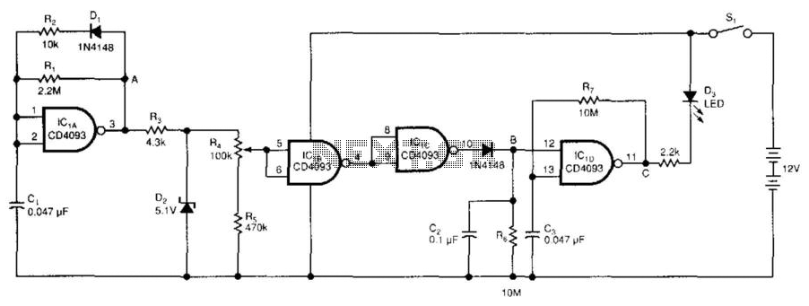
The low-voltage battery detector employs a CD4093 Schmitt trigger alongside a capacitor functioning as a 1-bit dynamic RAM. The circuit is designed to conserve power through a periodic testing method. Components IC1A, CI, R1, R2, and D1 produce a...
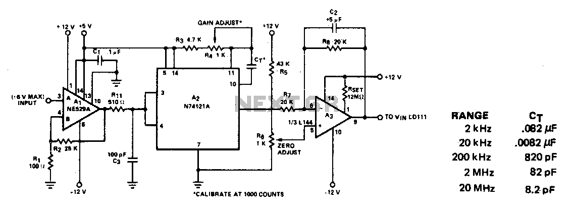
This circuit converts frequency to voltage by taking the average DC value of the pulses from the 74121 monostable multivibrator. The one-shot is triggered by the positive-going AC signal at the input of the 529 comparator. The amplifier acts...
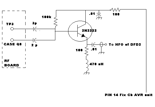
The back-to-back diodes are included because some radios generate high voltage transients when switching bands, which can cause the DFD to lock up, requiring a power cycle to reset. If the power for the backlit display is sourced from...
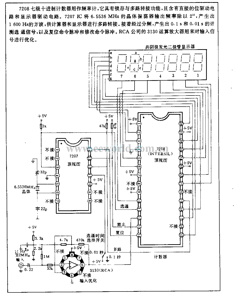
The 7208 seven-metric system counter is utilized as a frequency meter. It features a latch and multiplexing function and incorporates a direct drive circuit along with a display driver circuit. The 7207 IC divides the output frequency of a...
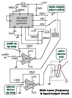
The aim of this project is to visually demonstrate the interactions of frequencies with one another. By utilizing mirrors and magnets to reflect a laser beam, a visual representation of the mathematical principles inherent in electronics is created. The...
The low-drift solid-state design for the 40-meter band exhibits a maximum frequency change of only 25 Hz from cold start to full warm-up at 25 degrees Celsius. After stabilization, the maximum frequency hunting is limited to 5 Hz. Drift...