
Digital Frequency Display

The installation of a remote VFO plug or RCA/BNC connectors is possible, depending on the user's preferences and willingness to modify the equipment. The BFO signal, approximately 3 volts peak-to-peak, can be tapped at two locations on the boards, while the Local Oscillator signal, about 3 volts peak-to-peak, is available at a designated test point. Two cabling options exist for routing the VFO signal, ensuring proper soldering and grounding connections for reliable operation. The VFO signal is also available at the remote VFO adapter plug, although some FT-101 versions may not provide sufficient amplitude for reliable DFD operation.The back to back diodes are there because some radios present high voltage transients when switching bands which will lock up the DFD requiring it to be turned off and back on to unlock. If power for the backlit display is to be taken from Vdc when AC is supplied to Vac then the capacitor from Vdc to gnd should be increased to about 100ufd to 250u
fd depending on current supplied to backlit. Piero used a DFD with the IC-202S two meter rig. It triples a 15MHz VXO to 45 MHz and then triples it again to 145MHz. Piero took the signal after the first tripler and set DFD to multiply by 3. The signal was taken from the junction of R25, R26 and C39 through a 100pf capacitor and about 12" of RG174U. I purchased your DFD and it works great. Although to get it to work with my Kenwood TS-820. I had to add an amp to the front end to beef up the VCO signal from my radio. I thought you would like to know that I used a Signetics NE5205 wide band 20db amp. I used two 1000pf caps, one on the input and one on the output. Also a. 01 bypass cap. I taped into the 5volts on your board and I was in business! I did a bench test and the DFD will convert a 50mvp-p signal up to 47Mhz. Which is well above where my radio VCO tops out at. I thought you would like this info and find it useful, if you didn`t already know about this chip. Thanks for bringing my radio up to modern standards. You can also use an NE5204. These devices have a 50 ohm input impedence. An emitter or source follower can be added to the input to increase the input impedence. Direct conversion units are simple. Connect to the LO (VFO) output and adjust the IF offset to zero. The NE/SE602 is a popular device in such units. The counter should be connected to pin 7 (the emitter of the oscillator transistor) Single conversion superhets are common in QRP transceivers and older vacuum tube receivers.
When connecting to a vacuum tube unit a resistor attenuator may be required. Put a resistor from the input to ground on the Zt pads provided on the PCB. Connect the unit through a series resistor and capacitor to the oscillator plate or cathode (if unbypassed). I`m using the DFD with a GE Superadio III. The Superadio is a $49. 95 AM/FM battery/ac (with internal power transformer) receiver and is a favorite of AM dx`ers. It has a tuned RF stage for AM, a very large loopstick antenna, a large speaker plus a tweeter, and a wide/narrow IF selectivity switch.
What it lacks is frequency calibration; my dial is off by maybe 10%. Looking at a web page for Superadio buffs, I find this is a universal complaint. (Radio Shack sells an Optimus "High Performance" radio that appears to be the same Chinese-made set). I use the DFD only for AM. The only place to get more than about 20 mv of LO signal is at the collector of the LO transistor, Q15 (middle pin).
This is right across the tuning varactor but the signal is still only about 1v pk. To minimize the capacitive load I built a dead bug style source follower using a 2N4416 (1. 1k source resistor to ground, 100k resistors from the gate to ground and from the gate to Vcc, Drain to Vcc, 10pf capacitor from the gate to the base of Q15). Vcc (4. 3V) is from the hot end of R16. Ground is the cold end of R17 (330 Oms). The supply voltage and ground for the DVD (10V) are across C55. (These are convenient places to make connections w/o removing the radio`s circuit board). From the top inside locate R12, a 1500 ohm resistor, located on the right edge of the printed circuit board.
Connect a 68pf capacitor at the end of R12 going to Q4 (other end is grounded). Connect the other end of the capacitor to a length of RG174 coax sufficient to reach your DFD. I`m not sure what the IF is for this receiver but I strongly suspect 455KHz. You can use that to start and verify by tuning in an AM broadcast station of known frequency and adjusting the offset and +/- jumper to display the correct frequency. DFD1-Atlas is programmed for automatic band selection when the radio is operated in the amateur bands only.
Display outside amateur bands may not be correct. The oscillator pre-mix type unit mixes a VFO with a crystal oscillator. Either the sum or difference frequency of that is filtered and sent to the RF mixer. The pre-mix output frequency is the main LO frequency. The IF offset should be set to the units IF frequency. ADD/SUBTRACT depends on if the main LO is above the RF frequency (SUBTRACT) or below (ADD). In some units it may be a function of which band it is set on. In that case it is necessary to have a switched input to the ADD/SUBTRACT input of the DFD. NOTE there is a bandpass filter tuned by the PRESELECT knob on the output of the LO mixer. DFD may not read right unless the PRESELECT is set at least close to correct for the frequency of operation. The LO is always high-side (above the RF frequency). This makes the maximum LO frequency 38. 83 MHz. With 2V p-p or more the DFD can be connected to the LO output at pin 4 of the RF unit (X44-1150-001).
This signal will have to be routed out of the unit. I suggest using high impedence shielded cable such as used for RCA type video cables between VCR and TV. I have developed a special version of the DFD (DFD2) which will measure three different frequency simultaneously, the crystal OSC, the VFO and the BFO.
It will then compute the carrier frequency of the RF for LSB, USB, AM and the zero beat carrier frequency of CW. It will automatically determine the operation mode as a function of BFO frequency and display LSB, USB, CW or AM.
There are custom chips for the following which offer jumper selectable 10/100Hz resolution and display using either "MHz" or dummy zeros to fill out 8 digits. ie: 14. 234. 56MHz or 14. 234. 560 (10Hz resolution) or 14. 234. 5 MHz or 14. 234. 500 (100Hz resolution). 1) You may use the remote VFO plug (octal) if: a. You are sure that you, or anyone else that you may sell the rig to in the future, will never want to install a Yaesu remote VFO; b.
You have a spare octal, male plug; c. You are willing to work in a very restricted space. 2) You may bring cables out of the rear of the rig and terminate them with RCA or BNC connectors at the Digital Frequency Display unit if: a. You are not concerned with affecting the resale value of the FT-101 by drilling holes in the rear panel; b.
You want to avoid soldering to an octal plug in a very congested location. 3) You may install RCA or BNC chassis mount jacks on the rear panel if: a. You want the modification to appear as inconspicuous as possible; b. You don ’t want cables that cannot be disconnected at the rear panel; c. You are willing to very accurately measure and drill mounting holes in a very small space. The BFO signal (3. 1793 mhz) is approximately a 3 volt (peak-to-peak) signal that may be tapped in either of two different places. It appears on pin 6 of board 1184A and is carried by a short piece of coaxial cable to pin 5 of board 1183A.
Each board has a convenient grounded pin for shield connection, but board 1183A is easier to reach with a small soldering iron. After routing the new cable (or mini-coax, which ever you have chosen) from the rear panel to the area of the board chosen, solder a.
01 disk ceramic capacitor to the center conductor of the cable. Then solder the free lead of the capacitor to the chosen pin of the board edge connector and the shield to the nearest grounded pin on the edge connector. The Local Oscillator signal (approximately 6 mhz above the displayed signal, or 8 to 36 mhz) is approximately a 3 volt (peak-to-peak) signal that is available at the test point near the top edge of board 1181A.
You have 2 cabling options here. The first option is to route the cable from the rear panel toward the front of the transceiver, and the openings around the tuning dial. Use these openings to pass the cable to the top of the chassis. While viewing the FT-101 from the normal operating position in front of the rig, route this cable up over the tuning shaft and to the right of the chassis.
Solder a. 01 disk ceramic capacitor to the center conductor and a small ground lug to the shield. Solder the free lead of the capacitor to the test point at the top of board 1181A, and attach the ground lug under the adjacent control ’s mounting nut and lock-washer. AN ALTERNATIVE installation method is to install the blocking capacitor (. 01 disk ceramic) on the board between the test point and unused pin 15. This will allow easy removal of board 1181A. However, it requires soldering the coax to the edge connector for board 1181A in a very congested area.
In this alternative installation the cable stays on the underside of the chassis and is soldered to pin 15, with the shield is soldered to pin 18 of the edge connector for board 1181A. The VFO signal (approximately 9 mhz) is about a 1 volt (peak-to-peak) signal available at pin 11 of board 1180A.
After routing the cable from the rear of the chassis, solder a. 01 disk ceramic capacitor to the center conductor. Solder the free capacitor lead to pin 11 and the shield to pin 10 of board 1180A. (The VFO signal also appears on the remote VFO adapter (octal) plug. In some versions of FT-101 ’s, this signal does not have enough amplitude to operate the DFD reliably. Your mileage may vary. ) 🔗 External reference
Related Circuits
The standard circuit will display directly in Hz (1MHz max), and there is a separate on board divider that will allow you to display directly in KHz (approx 40MHz max). Because the display reads directly in Hz or KHz...
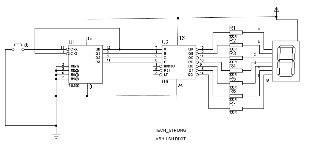
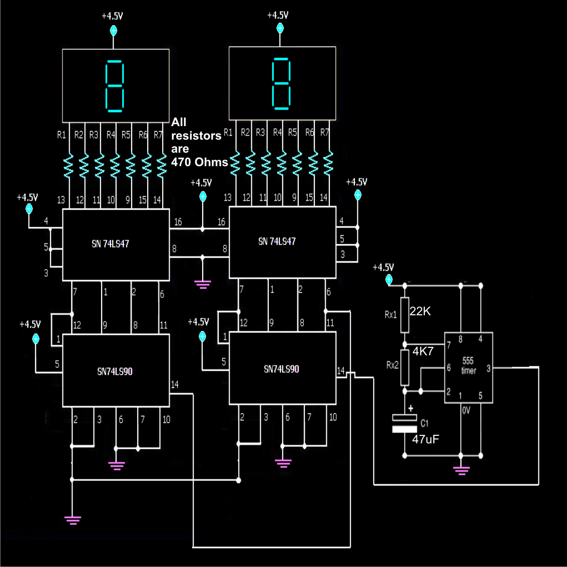
This project allows for the display of digits from 0 to 9 on a seven-segment display while counting the number of people entering a room. A counter IC, the 7490, is utilized alongside a BCD to seven-segment decoder IC,...
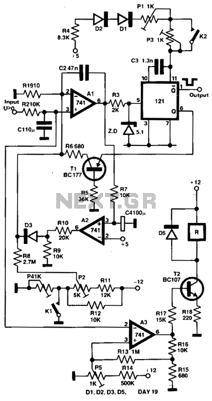
The output voltage of a thermocouple is converted into a frequency that is measured by a digital frequency meter. The output signal from the thermocouple is proportional to the temperature difference between the hot junction and a reference thermostat...
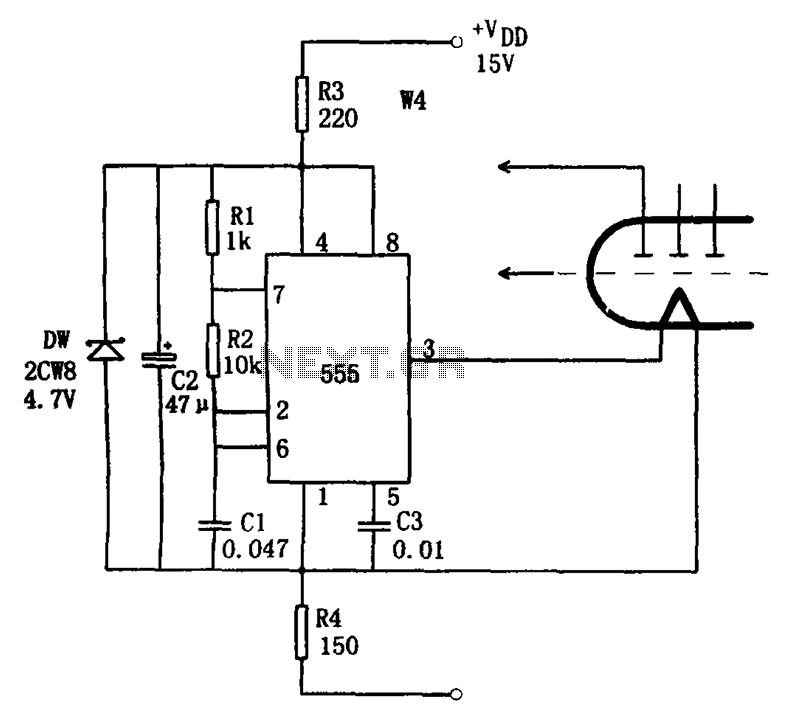
The economic fluorescent display circuit is illustrated in the figure. The primary component of this circuit is the 555 timer configured as a multivibrator. The oscillation frequency is determined by the components R1, R2, and C1, with a frequency...
A simple frequency counter circuit can be easily constructed by any electronics enthusiast for its intended purpose. The circuit diagram was provided by Mr. Kapital through an order on Fiverr. The functioning of the circuit involves generating positive voltage...
The 555 timer is utilized as a clock source to drive the RS7490 decimal counter, providing a BCD output to a 7-segment LED display. The clock frequency can be adjusted by changing the value of resistor R1. The circuit operates...