
The simple LED Flasher by IC 4011

The LED flasher circuit operates by utilizing a basic astable multivibrator configuration, which can be implemented using two transistors. This circuit alternates the state of the output, causing the connected LED to flash on and off at a specified frequency.
The core components of the circuit include two NPN transistors, resistors, capacitors, and a single LED. The transistors are arranged in a feedback loop where the output of one transistor is connected to the base of the other, allowing for continuous oscillation. The timing of the flashing is determined by the values of the resistors and capacitors selected for the circuit.
In a typical setup, the circuit begins with one transistor in the "on" state, which allows current to flow through the LED, causing it to illuminate. As the capacitor connected to the base of this transistor charges, it eventually reaches a threshold voltage that turns the transistor off. This action simultaneously turns the second transistor on, creating a cycle that repeats itself.
The frequency of the flashing can be adjusted by changing the capacitance or resistance values. For example, increasing the capacitance will result in a slower flash rate, while reducing the resistance will speed up the flashing.
This LED flasher circuit serves as an excellent introduction to basic electronic principles, including the behavior of transistors, capacitors, and resistors in a timed application. It is a practical project for beginners to gain hands-on experience with electronic components and circuit design.This is simple a led flasher circuit that I would link to suggest you make it.But before you can use transistors,which difficulty when we learn about digital.. 🔗 External reference
Related Circuits

A teardown of a BK Precision 4011 5MHz function generator revealed that, like most basic function generators from earlier times, the BK 4011 does not include frequency sweep as a standard option. However, it does feature a VCG (Voltage...
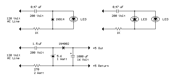
The circuit shown demonstrates how to power one or two LEDs from a 120-volt AC line by utilizing a capacitor to reduce the voltage and a small resistor to limit the inrush current. Because the capacitor needs to conduct...

For individuals seeking LED-based footswitching without the inconvenience of battery installation, a battery-less LED-based footswitch modification is being developed for 2-channel amplifiers. This solution is designed to work with the existing TRS jack and footswitch, and it will involve...

This oscillator may contain several switched crystals to provide channelized operation. A buffer amplifier may be added if desired. The oscillator described is designed to utilize multiple switched crystals, enabling it to operate across various frequency channels. This feature is...

The circuit presented is a simple audio amplifier capable of delivering 12W to an 8 Ohm speaker. The operational amplifier IC TL081 serves as the preamplifier in this design. Alternatively, any operational amplifier with compatible power supply ratings can...

The cycle is repeated only when the S7 switch at the Q1 output is pressed within the designated time frame. When all keys are pressed in the correct order and within the specified time, Q7 goes high for approximately...