
The Super Capacitor Flashlight with Custom Charger and Voltage Booster
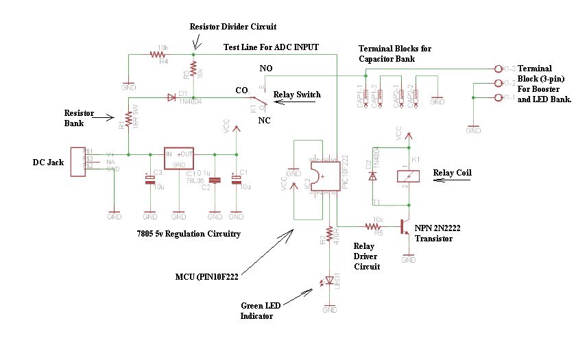
The circuit schematic is structured around four essential hardware blocks that facilitate the overall functionality of the system.
1. **Wall Transformer**: This block serves as the primary power source, converting the high-voltage AC from the mains supply into a lower voltage AC suitable for the circuit's requirements. Typically, a step-down transformer is employed to achieve the desired voltage levels, ensuring safe operation of subsequent components.
2. **Charging Circuit**: The charging circuit is responsible for converting the AC voltage from the wall transformer into a stable DC voltage. This is usually accomplished using a rectifier (either full-wave or half-wave) followed by a smoothing capacitor to filter out ripples, providing a steady DC output. This voltage is crucial for powering the control unit and other components effectively.
3. **Control Unit**: The control unit acts as the brain of the circuit, managing the operation of the entire system. It may incorporate a microcontroller or a dedicated logic circuit that processes input signals, executes programmed instructions, and controls the output stage based on predefined conditions. This block may also include various sensors and feedback mechanisms to monitor performance and adjust parameters dynamically.
4. **Output Stage**: The output stage is designed to deliver the final output of the circuit, whether it be a signal, power to another device, or any other form of output. This block may consist of amplifiers, drivers, or other components that ensure the output is at the required levels and formats for the intended application.
Each of these blocks is interconnected through a series of conductive paths, with careful attention paid to component ratings and specifications to ensure reliability and efficiency. The overall design must also consider aspects such as thermal management, electromagnetic compatibility, and safety standards to ensure optimal performance in real-world applications.Before I begin talking about the schematic, let it be known that there are four hardware blocks to this circuit: 1) The wall transformer 2) The charge.. 🔗 External reference
Related Circuits
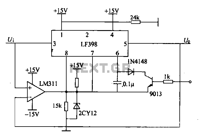
The peak voltage sample and hold circuit is illustrated in Figure 12-50. This circuit comprises the LF398 sample and hold chip and the LM311 voltage comparator. The LF398 is responsible for outputting and inputting voltages. The LM311 compares the...
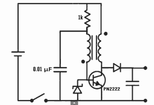
Excellent Joule thief circuit idea! The Joule Thief is a simple yet effective circuit designed to extract usable voltage from low-voltage power sources, such as depleted batteries. This circuit operates on the principle of boosting voltage through the use...
Voltage variations and power cuts adversely affect various equipment such as TVs, VCRs, music systems, and refrigerators. This simple circuit will protect the costly equipment from high as well as low voltages and the voltage surges (when power resumes)....
Features: 1. The operating voltage is low, functioning with a single supply of 2.0V. 2. Power consumption is minimal, with a supply current of 5 µA at 32 kHz and 130 µA at 1 MHz. 3. It has a...
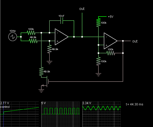
This circuit is a voltage-controlled oscillator, which is an oscillator whose frequency is determined by a control voltage. A 10 Hz sawtooth oscillator provides the control voltage in this case; this causes the frequency to rise slowly until it...
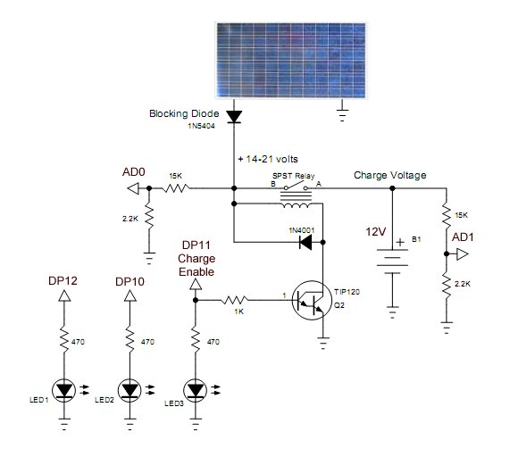
Construction and programming of a PICAXE solar panel battery charge controller. The PICAXE solar panel battery charge controller is designed to manage the charging process of batteries using solar energy. This system typically involves several key components: the solar panel,...
Warning: include(partials/cookie-banner.php): Failed to open stream: Permission denied in /var/www/html/nextgr/view-circuit.php on line 713
Warning: include(): Failed opening 'partials/cookie-banner.php' for inclusion (include_path='.:/usr/share/php') in /var/www/html/nextgr/view-circuit.php on line 713