
The switch shut off time delay circuit diagram
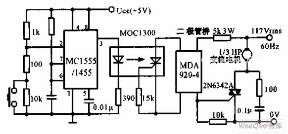
The switch shut-off time delay circuit is designed to control the duration for which an AC load remains energized after a control button is released. The core components include a timer IC that governs the time delay, optocouplers for isolation and signal transfer, and a bridge SCR configuration that facilitates the control of AC loads.
When the control button is pressed, the circuit is powered, and the timer begins its countdown. The voltage at pin 2 is reduced to one-third of the supply voltage (Ucc/3), which is essential for the operation of the timer. As the timer counts down, the output at pin 3 transitions from a low to a high state, which activates the LED indicator, providing visual feedback that the circuit is operating.
The optocouplers serve to isolate the control logic from the high-voltage AC side, ensuring safety and preventing damage to sensitive components. The bridge SCR is employed to handle the AC switching, allowing for the control of high-power loads without mechanical switches. This arrangement not only enhances durability but also minimizes wear and tear on components.
Once the timer completes its countdown, the output at pin 3 will drop, turning off the LED and deactivating the SCR, which in turn cuts off the AC power to the load. This design is particularly useful in applications where a delayed shut-off is required, such as in motor control, lighting systems, or other automated processes where a temporary delay is beneficial. The entire circuit can be powered from a standard AC source, and with appropriate component selection, it can be tailored for various load requirements and time delays.The switch shut off time delay circuit is shown as below. The switch shut off time delay circuit is composed of the timer, optocouplers, bridge SCR, SCR AC switch. When the control button is released, the keeping motor or other AC start power for 1 hour. Button closure. 2 pin voltage step-down Ucc / 3 below. The output pin 3 rises. LED lights. The bridge S.. 🔗 External reference
Related Circuits
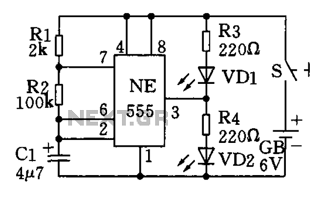
The circuit utilizes a 555 timer as the central component of a flashing light circuit. In normal operation, the light-emitting diodes (LEDs) VD1 and VD2 alternate flashing. The circuit comprises the NE555 timer, resistors R1 and R2, and capacitor...
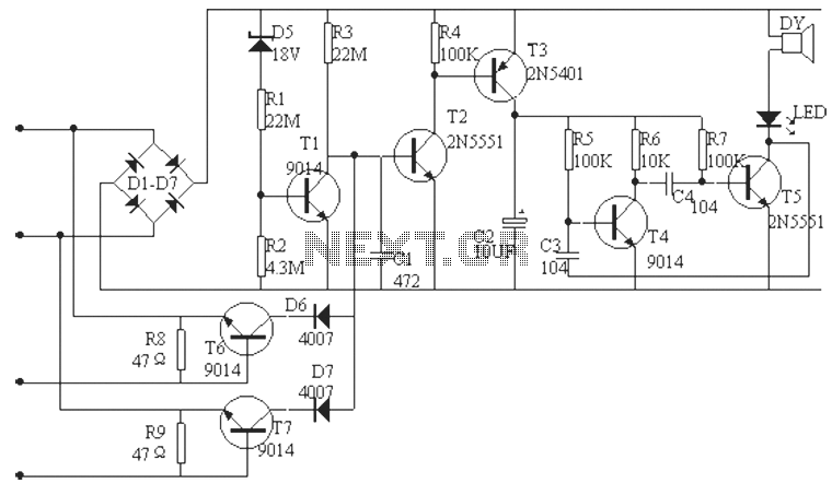
The phone alarm device is designed to monitor and prevent unauthorized use of a telephone line. When interference signals are detected on the line due to theft attempts, the alarm activates, preventing the thief from making calls while alerting...

The circuit of this 30W audio amplifier produces clear audio output quality. The circuit module does not have any improvements. It utilizes a Darlington pair in the transistor configuration. The 30W audio amplifier circuit is designed to deliver high-fidelity sound...
This project utilizes a microcontroller that is programmed with software available on the Gernsback BBS at 516-293-2283 as part of RUNABOUT.ZIP. The robot can be operated using a universal remote control. The project involves the integration of a microcontroller, which...
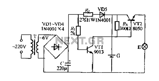
Figure 282 illustrates a simple emergency lamp circuit designed to activate during a power outage. The circuit utilizes a transformer (T) for voltage stepping, diodes (VD1 to VD4) for rectification, and a capacitor (C) for smoothing the output. During...
The application that we propose is a simple filter that limits the acoustic region (20-20000Hz) to the region 20-100Hz. With the manufacture proposed, an active filter can be created to drive a loudspeaker for very low frequencies. This allows...