
Blackout emergency lights circuit 2
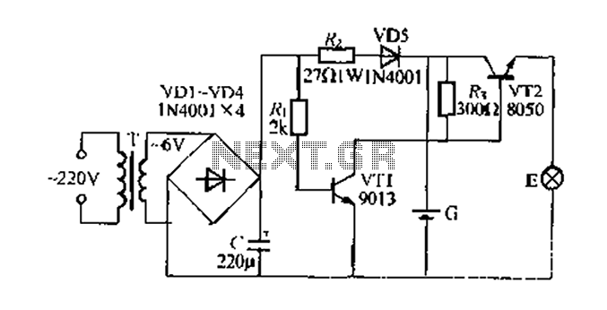
The emergency lamp circuit is designed for reliable operation during power outages, ensuring that illumination is maintained when the main power supply fails. The transformer (T) steps down the line voltage to a suitable level for the circuit components. The rectification process is accomplished using diodes VD1 through VD4, which convert the alternating current (AC) from the transformer into direct current (DC). The capacitor (C) smooths the rectified output, providing a stable voltage to charge the battery (G).
When the main power is available, the circuit operates in a standby mode. The current flows through the circuit, charging the battery while keeping transistor VT1 in the off state. This configuration ensures that the small lamp does not illuminate during normal operation, conserving battery power for use during an outage.
Upon loss of mains power, diode VD5 prevents the battery from discharging back into the grid. The absence of voltage at the base of VT1 causes it to turn off, which in turn allows VT2 to become active. The base of VT2 receives bias from the charged battery, enabling it to conduct and power the emergency lamp. This design allows for a seamless transition from grid power to battery power, ensuring that the emergency light is activated promptly during a power failure.
The circuit's components are selected to meet standard operational requirements, and no specific parameters are needed beyond those depicted in Figure 282. This circuit is suitable for various applications, providing an essential safety feature in residential and commercial settings.Figure 282 foot another simple power outage should emergency lamp circuit. When the grid is often only power and municipal electricity by T Buck, VD1 ~ VD4 rectification, C- cr ossing and filtered through R. And VD5 to the battery (; charged at this time,. VT1 closing R. positively skewed by conduction, its collector is low, so V, r2 is turned off, a small lamp is not lit when the mains F. LU sudden power outage, due to the isolation VD5, G will not supply power to the pole by R. VT1 base, VT] and idle power cut off, thereby lifting the VT2 blockade, VT2 base due by foot from the battery G obtained bias conduction, Eagle will be powered emergency lights E hair light, thin pressure device T, the battery (G small and light E to seek common ground seven cases, the other component parameters Figure, no special requirements.
Related Circuits
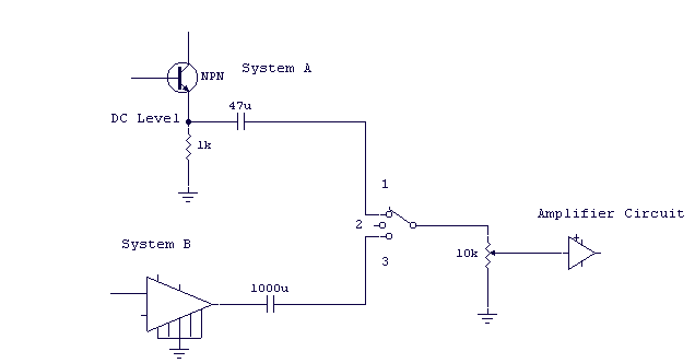
You may be familiar with this effect. You switch audio equipment such as an amplifier to a different input and there is a loud click or "thump" in the speaker system. Not all equipment is affected. Some high-end audio...
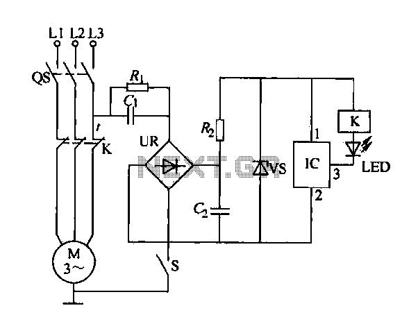
The electric sewing machine saving circuit is designed with a Hall switch integrated circuit (IC) and a relay (K). When the switch is closed, power is activated. The circuit includes a resistor (R) and a capacitor (Ci) for RC...
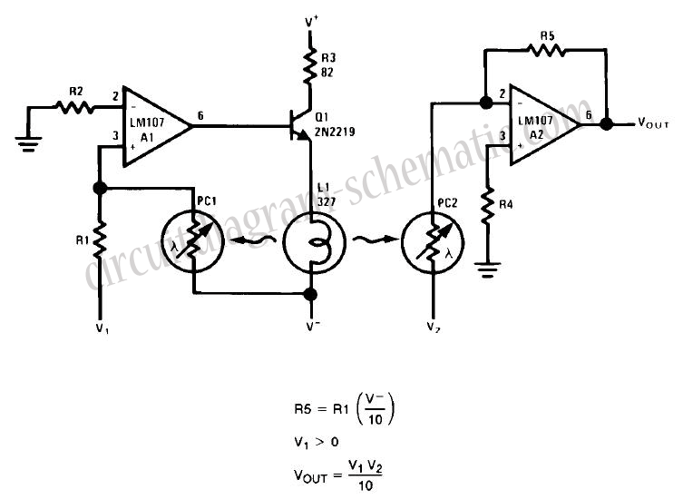
This circuit is a simple analog multiplier. The operation of the circuit can be understood by considering A2 as a controlled gain amplifier that amplifies V2, with its gain dependent on the ratio of the resistance of PC2 to...
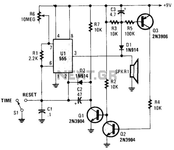
This circuit operates in astable mode and produces a tone at the end of the first period, which can last several minutes. When switch SI is in the time position, transistor Q3 is turned off because pin 3 of...
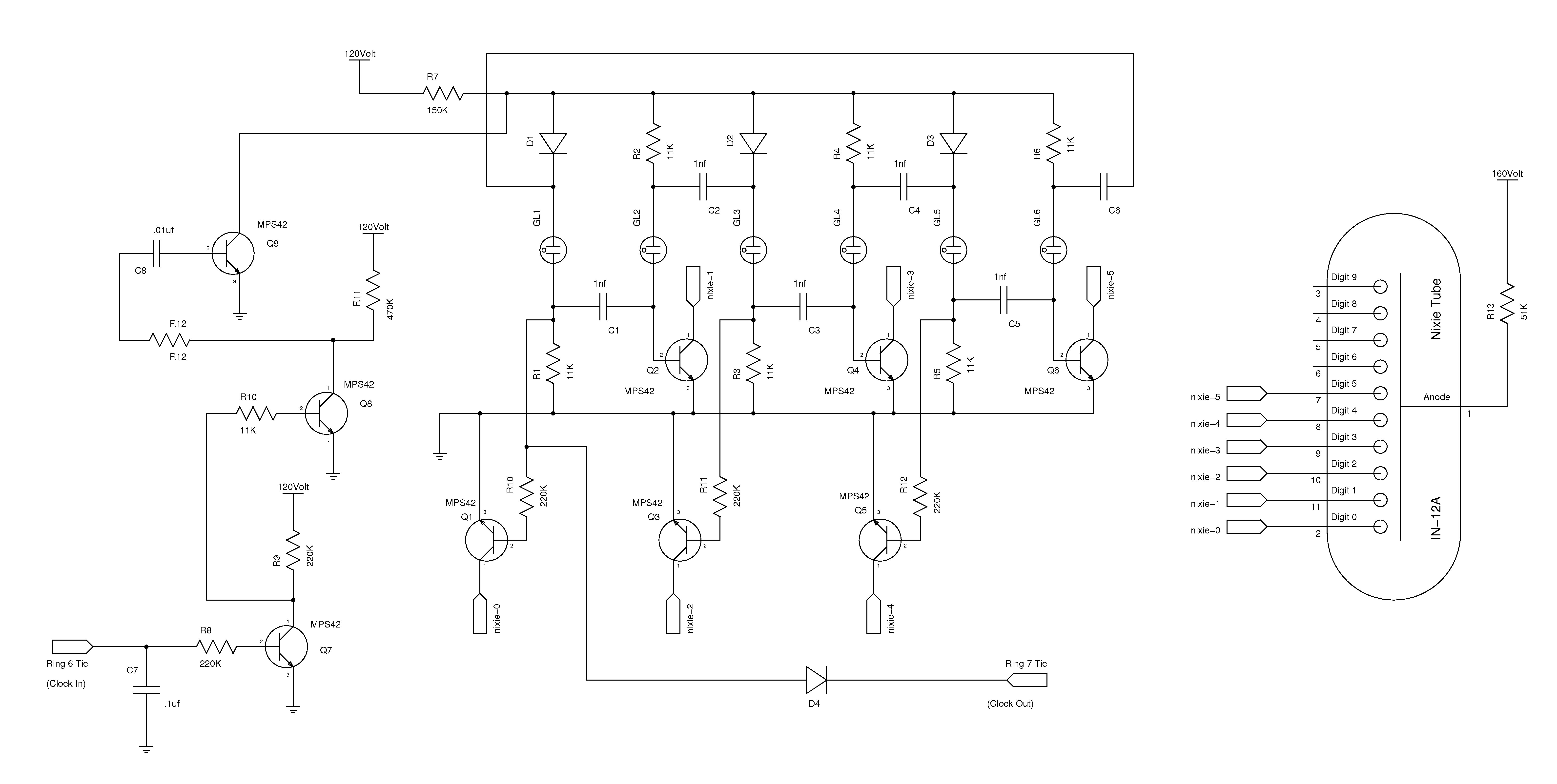
The nixie tube clock consists of a high-voltage power supply, seven ring counters, and an Atmel AVR processor. The power supply is shown in Schematic 1. It takes 12 volts AC and converts it to DC, which drives the...
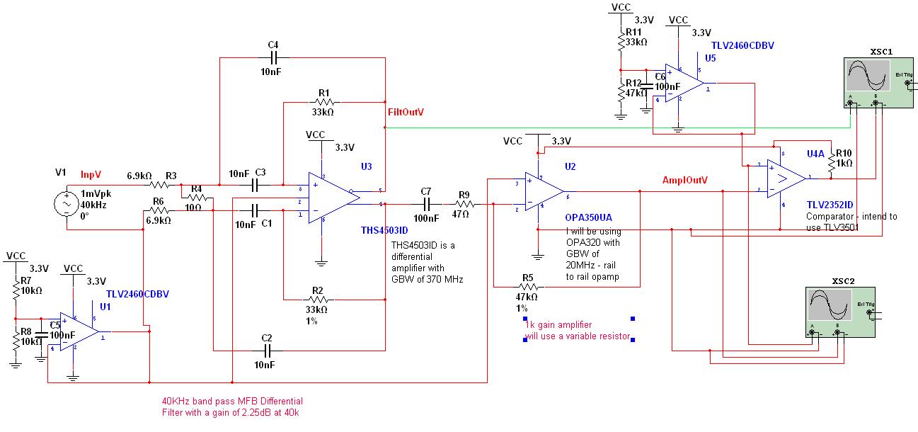
A circuit has been designed to detect the duration of an ultrasonic pulse as it travels a certain distance. The input signal is sourced from a 40 kHz ultrasonic receiver. The first stage consists of a 40 kHz band-pass...