
The use of low frequency oscillation base 555 circuit made flashing light circuit Circuit II

The described circuit employs the NE555 timer in astable mode, which is essential for generating a continuous square wave output. The resistors R1 and R2 set the charge and discharge times of the capacitor C1, thereby determining the frequency of the output signal. The formula for the frequency (f) of the oscillator can be expressed as:
f = 1.44 / ((R1 + 2 * R2) * C1)
This equation highlights the relationship between the values of R1, R2, and C1 in controlling the timing characteristics of the circuit. The duty cycle, which indicates the proportion of time the output is high versus low, can also be adjusted by varying the resistor values.
The output from pin 3 of the NE555 timer is connected to the anodes of the LEDs VD1 and VD2 through appropriate current-limiting resistors to prevent excessive current that could damage the LEDs. The cathodes of the LEDs are connected to ground. When the output is high, current flows through VD2, illuminating it while VD1 remains off. When the output is low, the situation reverses, allowing VD1 to light up while VD2 turns off.
To enhance visibility, especially in outdoor or bright environments, different colored LEDs such as red, green, or yellow can be utilized. This not only aids in distinguishing between the two LEDs but also adds aesthetic value to the circuit. The overall design is simple yet effective for applications requiring visual signaling or decorative lighting, making it suitable for various electronic projects. As shown circuit 555 is at the core of the flash circuit, when their normal work, the light emitting diode and VD2 will VDl alternating flashing circuit principle summarized as follows: The base circuit NE555 and Rl, R2, Cl composed of low-frequency oscillator. After the start-up circuit, time base circuit 555 is 3 feet high and low potential of changing, when 3 feet high when, VDl loss of power does not emit light, VD2 powered light; when 3 feet is low, VDl powered luminous, VD2 loss of power It does not emit light. Therefore, the two light-emitting diodes will flash alternately light. When specific production, the two light-emitting diodes use red, green or yellow, some of the difference may be more visible.
Related Circuits
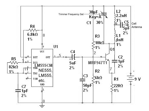
This device functions as a reversal of a radio station, sending a null signal to a selected frequency to eliminate the actual broadcast. The radio transmitter operates at a loss of 10,000W; therefore, this circuit is intended for use...
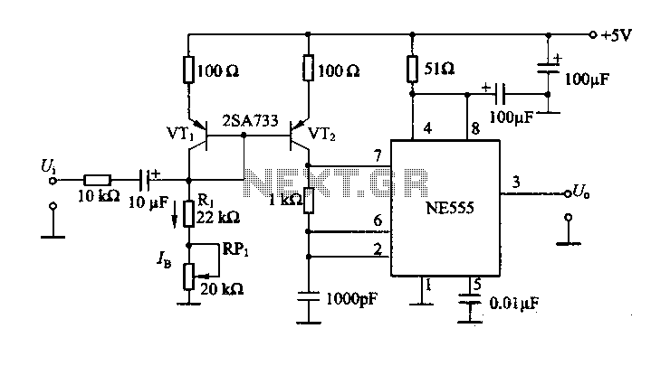
The circuit consists of a NE555 timer and a frequency modulation circuit that modifies the self-excited multivibrator NE555 by adjusting the charging current for frequency modulation. The components VT1 and VT2 form a current mirror circuit, which generates a...
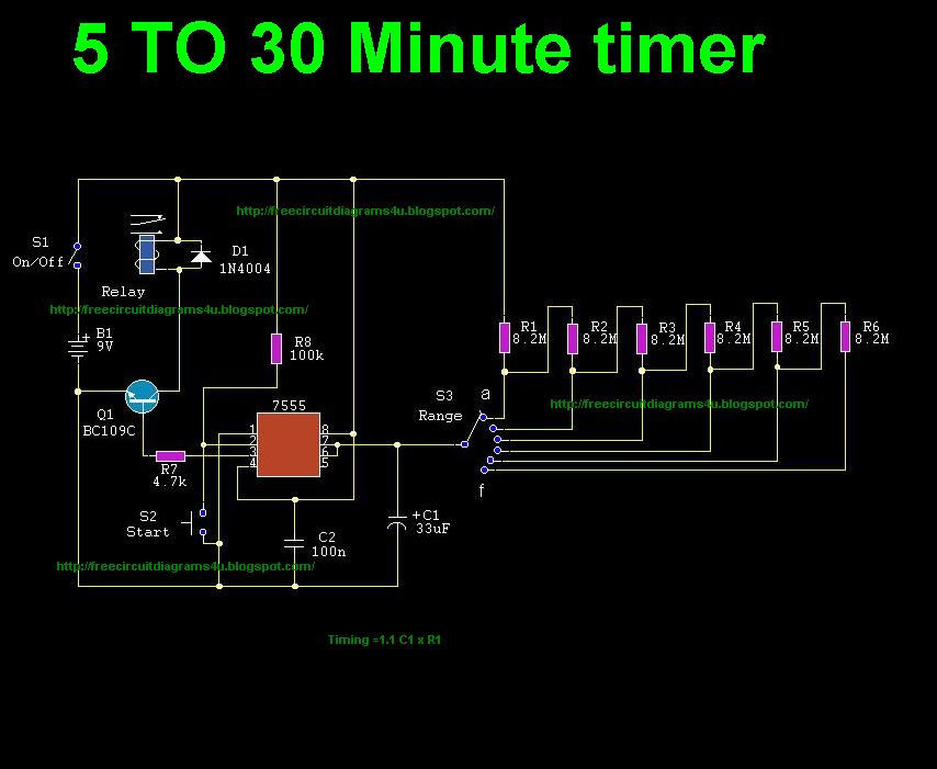
This circuit illustrates the use of the 7555 integrated circuit (IC) for a timer circuit that can be set to operate between 5 to 30 minutes. This circuit is beneficial as it allows for timed operations. The 7555 timer IC...
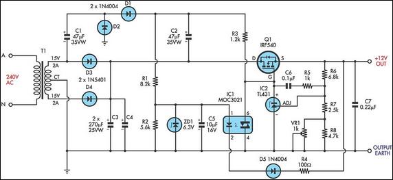
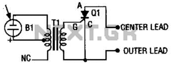
This circuit is a MOSFET-based linear voltage regulator with a voltage drop as low as 60 mV at 1 A. It utilizes a 15V-0-15V transformer and an IRF540 N-channel MOSFET (Q1) to provide a regulated 12V output. The gate...
The photo strobe slave trigger circuit utilizes a solar cell and a silicon-controlled rectifier (SCR) to activate any strobe light when triggered by a master strobe. The small solar cell generates a minimal voltage when illuminated. The photo strobe slave...
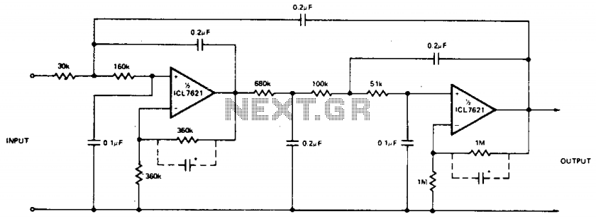
The low bias currents allow for the utilization of high resistance and low capacitance values, facilitating a low frequency cutoff at fc = 10 Hz, with an AVCL of 4 and a passband ripple of 0.1 dB. Additionally, small...