
Theft preventer alarm
The circuit primarily consists of a 555 timer IC, resistors, capacitors, a speaker or buzzer, and a thin wire that serves as a triggering mechanism. In the astable mode, the 555 timer continuously oscillates between its high and low states, generating a square wave output. This output can be connected to a piezoelectric buzzer or speaker, which converts the electrical signal into audible sound.
The triggering mechanism involves placing a thin wire in a position where it can be easily disrupted by unauthorized access. When the wire is broken, it alters the voltage levels at the input of the 555 timer, causing it to transition from a low state to a high state, thereby activating the output. The resistors and capacitors in the circuit determine the frequency and duty cycle of the oscillation, which can be adjusted to change the sound frequency produced.
Power supply considerations are crucial for this circuit. It typically operates on a DC voltage source, which can be a battery or an external power supply. Proper selection of components is essential to ensure reliable operation and to prevent false alarms due to environmental factors.
This alarm system can be further enhanced by incorporating additional features such as LED indicators to signal activation, or a delay circuit to prevent accidental triggering. Overall, this simple yet effective alarm circuit can serve as a valuable deterrent against theft and unauthorized entry.This circuit utilising a 555 timer IC can be used as an alarm system to prevent the theft of your luggage, burglars breaking into your house etc. The alarms goes ON when a thin wire, usually as thin as a hair is broken. The circuit is straightforward. It uses a 555 IC wired as an astable multivibrator to produce a tone of frequency of about 1kHz w hich gives out a shrill noise to scare away the burglar. 🔗 External reference
Related Circuits

The circuit alerts car drivers when the air temperature near the ground approaches 0°C, indicating a potential formation of ice on the road surface. Operational amplifier A1 is configured as a voltage level sensor, while operational amplifier A2 is...

The primary objective of this design is to address a minor flaw in the well-known Fridge Door Alarm circuit, which has been available on this website since 1999 and has been constructed by numerous hobbyists. This circuit unfortunately ceases...
This is a simple circuit of a beeper using a 555 timer. This circuit can be employed to energize lights, horns, or other signaling devices at any desired interval. The 555 timer is a versatile integrated circuit widely used in...
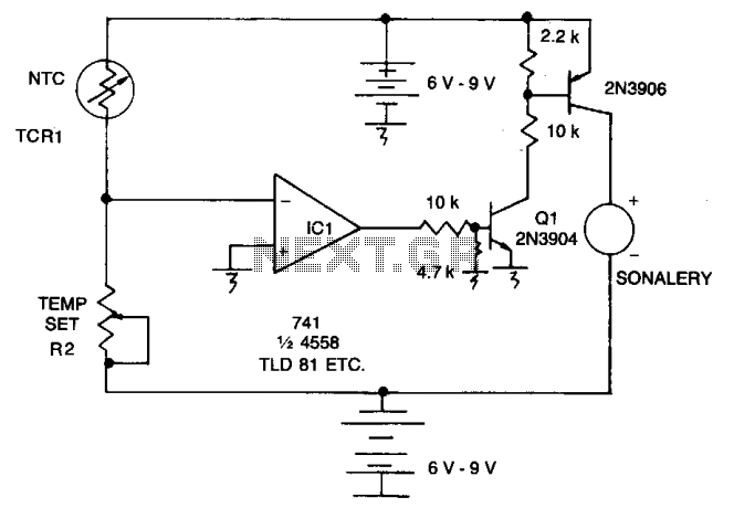
As the resistance (Rl) increases with a decrease in temperature, the output of integrated circuit IC1 becomes positive, activating transistor Q1. When Q1 conducts, it also triggers transistor Q2, which in turn activates the audible alarm. The threshold level...
The objective is to enhance information transmission through the distribution of articles. Please contact us via email at [email protected] within 15 days if there are any issues related to article content, copyright, or other concerns. Prompt deletion will occur...
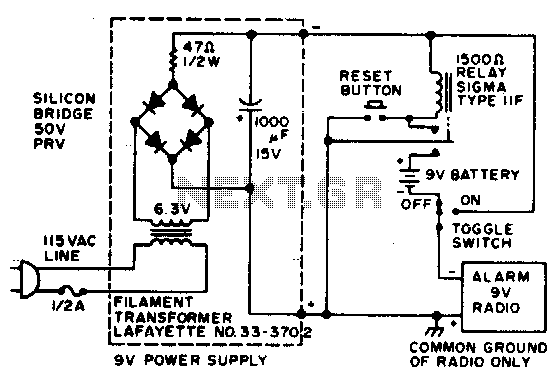
In the event of a power failure, the radio alarm activates without producing a loud siren, bell, or whistle. The alarm remains active even after power is restored and will continue until the RESET button is pressed. The described circuit...