
Ice warning alarm 12V

The output from A1 is driven into positive saturation immediately, as it operates in an open-loop configuration. This positive output voltage supplies power to A2 via its V+ connection on pin 9, initiating the oscillator. The thermistor used is a glass bead type with a resistance of about 20 kΩ at 20°C. The variable resistor VR1 is adjusted so that the lamp begins to flash when the air temperature reaches 2°C.
The circuit design employs two operational amplifiers to effectively monitor and react to temperature changes. The first op-amp (A1) functions as a comparator, where it continuously compares the voltage generated by the thermistor with a reference voltage. The thermistor's resistance decreases with a drop in temperature, causing the voltage at pin 1 of A1 to change accordingly. When the ambient temperature approaches 0°C, the voltage at pin 2 of A1 rises above the reference voltage at pin 1, resulting in a high output signal.
This output signal is critical for the operation of the second op-amp (A2), which is configured as an astable multivibrator. The astable multivibrator continuously oscillates between its high and low states, producing a square wave output. The frequency of this oscillation is determined by the values of the resistors and capacitors in the circuit, specifically designed to create a flashing effect at approximately 1 Hz. The current buffer transistor Tr1 amplifies the output from A2, allowing it to drive the filament lamp effectively without overloading the op-amp.
The thermistor's characteristics are crucial for the circuit's functionality, providing a reliable means of detecting temperature changes. The adjustment of VR1 allows for calibration of the circuit, ensuring that the lamp activates at the desired temperature threshold. This feature is particularly important for applications in automotive safety, where timely warnings of icy conditions can prevent accidents. Overall, this circuit serves as an essential tool for enhancing driver awareness and safety in potentially hazardous weather conditions.The circuit warns car drivers when the air temperature close to the ground approaches 0°C, thereby indicating possible formation of ice on the road surface. Op amp A1 is wired as a voltage level sensor. Op amp A2 is wired as an astable multivibrator which, by means of current buffer Trl, flashes a filament lamp at about 1 Hz.
As air temperature falls, a point is reached when the voltage at pin 2 just rises above the voltage at pin 1. The output of A1 is immediately driven into positive saturation, since it is operated open loop. This positive output voltage powers A2 through its V + connection on pin 9, starting the oscillator. The thermistor is a glass bead type with a resistance of about 20 ?? at 20°C. VR1 is adjusted so that the lamp starts flashing when the air temperature is Tto 2°C. 🔗 External reference
Related Circuits

In the event of a power failure, the radio alarm activates without producing a loud siren, bell, or whistle. The alarm remains active even after power is restored and will continue until the RESET button is pressed. The described circuit...

For many years, electromagnetic relays have been utilized as switches for controlling high-voltage devices. However, due to their large size and the noise they produce (both electrical and mechanical), TRIACs combined with opto-couplers have emerged as a more effective...
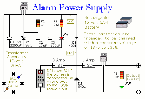
This Power Supply is suitable for the Modular Burglar Alarm. However, it has other applications. It is designed to provide an output of 12-volts, with a current of up to 1-amp. In the event of mains failure, the back-up...
Take care with transmitter circuits. It is illegal in most countries to operate radio transmitters without a license. Although only low power this circuit may be tuned to operate over the range 87-108MHz with a range of 20 or...

A circuit that offers visual indication of fluid level in a vessel, with a switchable audible alarm. Example uses would be to monitor the level of water in a bath or cold storage tank. Conductance is the reciprocal of...

This circuit is a simple 12V DC to 220V AC inverter that produces an AC output at line frequency, specifically 220V AC, or other voltages by selecting transformer T1. The 555 integrated circuit (IC) is configured as a low-frequency...