
Numeric water level indicator- liquid level sensor circuit diagram with 7 segment display
The circuit operates by monitoring the levels of a reservoir and encoding the sensed values into a binary format suitable for display. The 74148 IC encodes up to eight input lines into three output lines, allowing for efficient data representation. The outputs of the 74148 are then connected to either a HEX display or a 7447 decoder driver, depending on availability and project requirements.
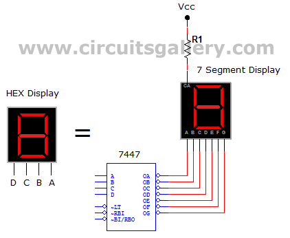
In the case of using the HEX display, the 4-bit binary input, which is derived from the sensed levels, directly corresponds to a hexadecimal digit, simplifying the process of visual representation. The HEX display eliminates the need for additional decoding, allowing for a straightforward connection to the encoder outputs.
If opting for the 7447 decoder driver with a standard 7-segment display, the circuit retains its functionality, although it requires the additional step of decoding the binary output. The 7447 converts the binary input into a format that can drive the 7-segment display, illuminating the appropriate segments to represent the encoded value visually. The design acknowledges that the fourth input of the 7447 is not required for this application, as the maximum encoded value is seven (binary 111).
This circuit design is advantageous for projects requiring level monitoring and display, providing a clear and efficient means to visualize data. It is adaptable to component availability while maintaining functionality and clarity in the representation of reservoir levels. Proper attention to the connections and power supply for the ICs and display components is essential to ensure reliable operation.Here we define 7 levels in thereservoir. The sensed values are connected to an encoder circuit. The encoder circuit consist of a 74148 IC, which is a 8 line to 3 line encoder. Next section is the HEX Display` which is a special type of 7 segment display. It is easier to use than the regular seven-segment display because it is already decoded. Each hexadecimal digit is displayed when its 4 bit binary equivalent is received as input, as shown in the truth table below. If it is difficulty to get a HEX Display` you can use ordinary 7 segment display with decoder driver IC 7447.
Hence the encoded values are displayed. This circuit will be really helpful for your project. You can neglect the 4th input (D) of 7447 because we are using this circuit to code up to 7 level, that is upto binary 111. Hence there is no need of the 4th input of 7447. 🔗 External reference
Related Circuits
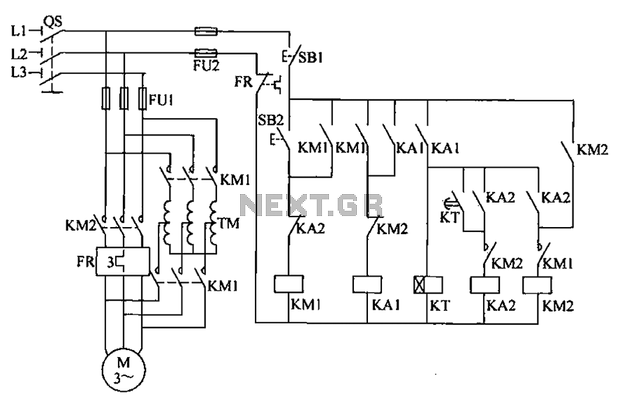
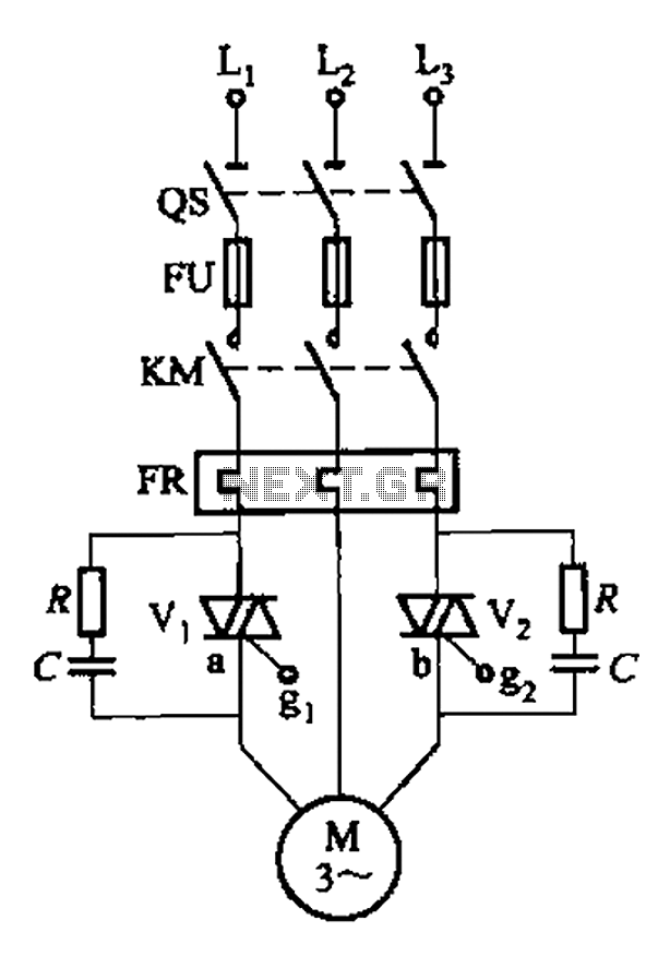
To initiate the system, turn off the power switch, then press the start button SB2. The KM1 contactor is energized, engaging self-locking, and closing the main contacts. The autotransformer TM is connected between the power source and the motor,...
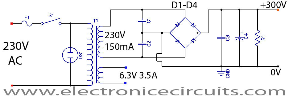
This is a successful vacuum tube project featuring a small amplifier where a 6V6GT output pentode is connected in triode mode, producing an output of approximately 4.5 watts. The project includes a single-ended audio amplifier with a resistive input...
This circuit consists of a 6 Zone Alarm system with an LED display. The alarm system features 6 independent zones and includes a 7-segment LED display, along with one timed entry/exit zone. The 6 Zone Alarm system is designed to...
The circuit depicted in Figure 3-80 is responsible for controlling a portion of the transistor multivibrator. A multivibrator serves as a robust positive and negative feed-forward amplifier, consisting of two branches that are interconnected through a coupled RC timing...
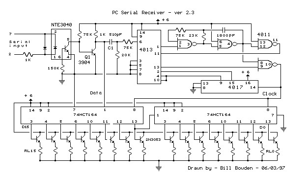
This circuit requires physical connections to be made to the computer's serial port (COM1 or COM2). It is generally considered difficult to cause harm to oneself or the computer through improper connections to this port; however, there is no...
The circuit is designed to deliver a surge current of 12 amps, offering performance that meets or surpasses that of typical commercial units. Additionally, it incorporates a current limiting feature, providing a level of reliability that is superior to...