
thermometer based on mikrokontroler
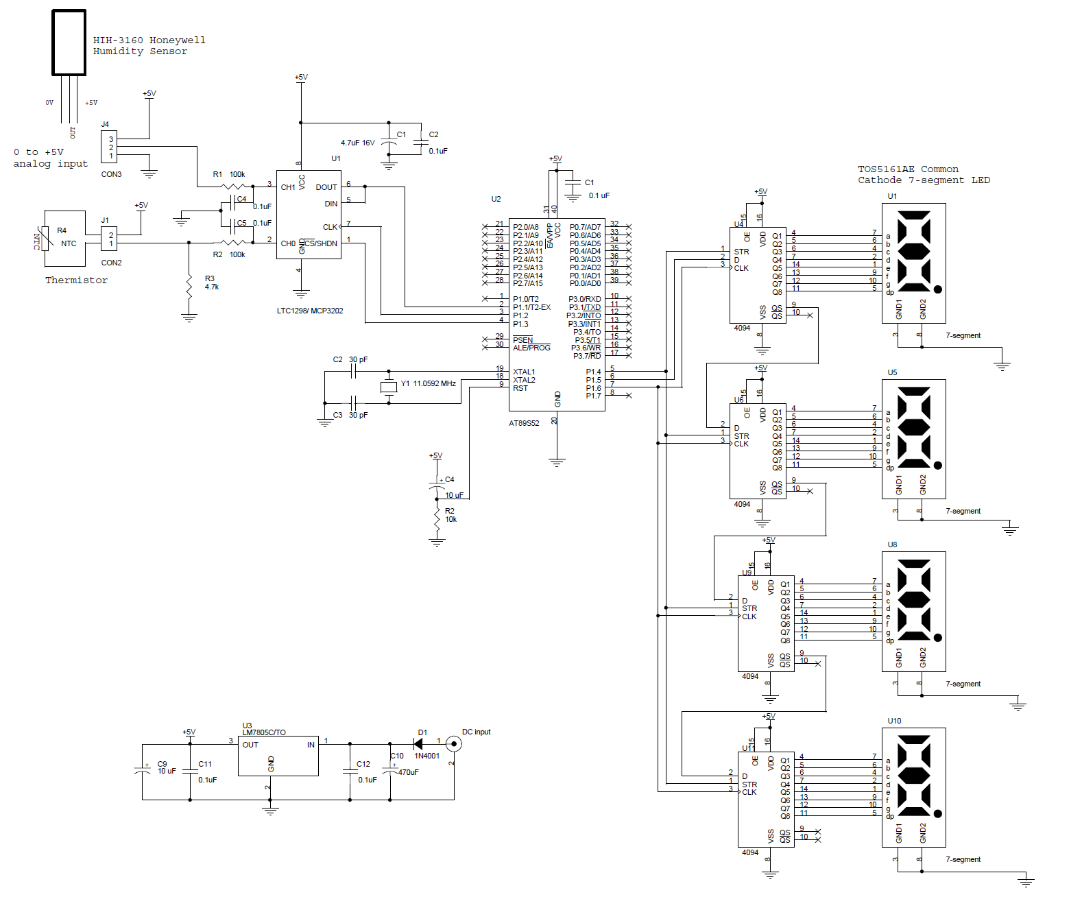
The circuit design integrates several key components to achieve accurate temperature and humidity readings. The AT89S52 microcontroller serves as the central processing unit, executing the C language program that manages data acquisition, processing, and display. The LTC1298 ADC is crucial for converting the analog signals from the thermistor and humidity sensor into digital data for the microcontroller to process.
The thermistor, which is a temperature-sensitive resistor, is configured in a voltage divider arrangement to produce a voltage proportional to the temperature. This voltage is then fed into the ADC's channel 0. The LTC1298 ADC features a 12-bit resolution, allowing for precise digital representation of the analog input, which is essential for achieving a sensitivity of 0.1°C in temperature measurements.
Channel 1 of the ADC is reserved for additional sensors, providing flexibility for future expansions or modifications to the system. In this setup, the HIH-3160 sensor is utilized to measure relative humidity, enhancing the functionality of the device beyond simple temperature readings.
The output from the ADC is communicated to the AT89S52 microcontroller via the SPI interface, utilizing pins P1.1, P1.2, and P1.3 for data transfer. This interface allows for efficient and rapid communication between the ADC and the microcontroller, ensuring timely updates to the displayed readings.
The display subsystem consists of a 0.5-inch four-digit 7-segment LED display, which is driven by a CMOS shift register (4094). This configuration allows for compact and efficient control of the display segments, enabling clear visibility of the temperature and humidity readings. The design effectively combines the necessary components to create a reliable and user-friendly thermometer and humidity measurement system.This is a circuit of a microcontroller AT89S52 thermometer and LTC1298 12-bit ADC, programs written in C language program with digital filtering and interface the LED display. Reading provides a sensitivity 0. 1C. The hardware block and circuit diagram is shown in the figure below. The thermistor sensor is epoxy. The signal conditioning circuit is a simple voltage divider. The ADC is 12-bit SPI interface LTC1298 analog to digital. Atmel`s Microcontroller 89S52. The 0. 5 inch display has four digits of 7 segments. The driver of the segment offers 32-bit CMOS output. The 12-bit ADC (LTC1298 or MC3202) are two channels, CH0 and CH1. The signal from ADC input channel 0 thermistor voltage divider is simple. Channel 1 is available for other sensors. The example shown in the diagram is the HIH-3160 Honeywell Relative Humidity Sensor. The ADC chip interconnects with MCU 89S52 with P1. 1, P1. 2 and P1. 3. The LED display has 4 digits. The CMOS shift register 4094 directly drives the LED 🔗 External reference
Related Circuits
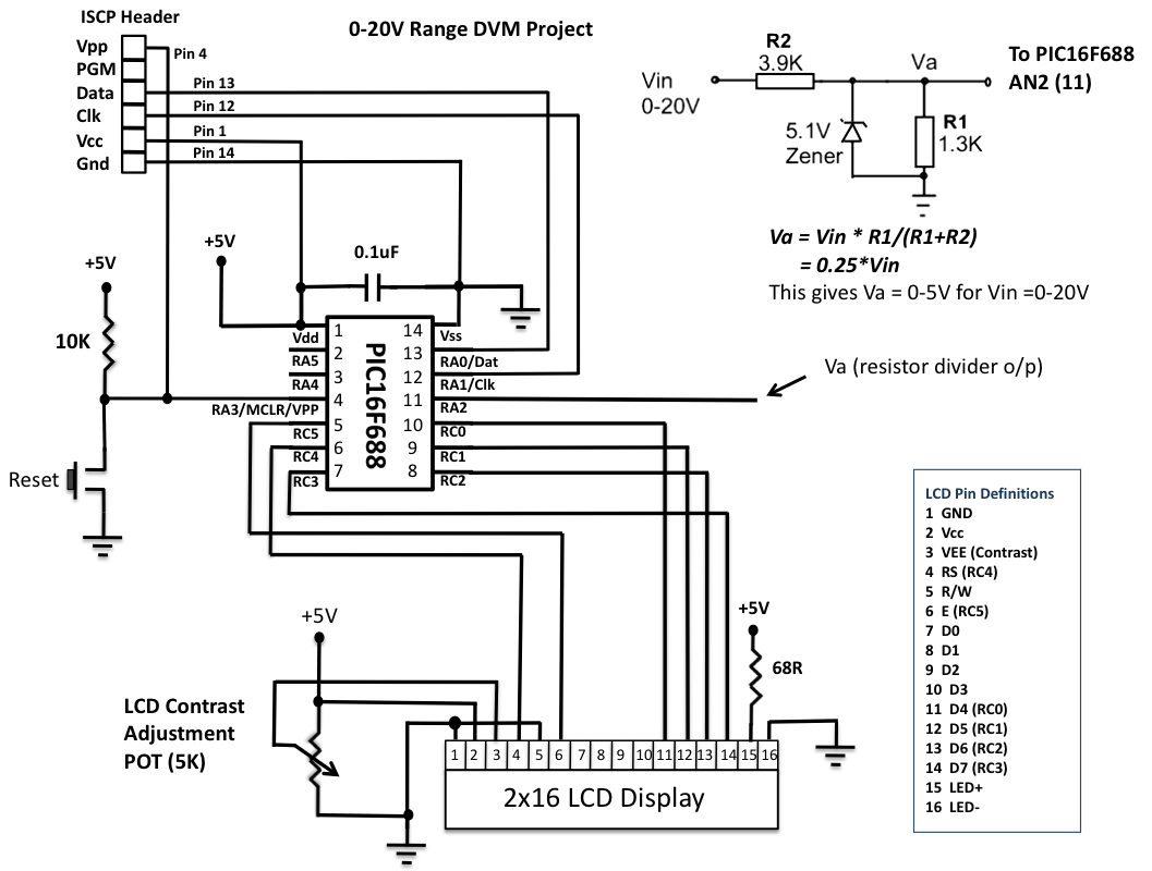
This is another version of an older digital voltmeter (DVM) project that was based on the PIC12F683 microcontroller. The previous version displayed the measured voltage on an LCD driven serially by the PIC12F683 using three I/O pins. The new...
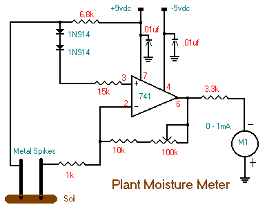
The following circuit illustrates a Plant Moisture Meter Circuit Diagram. This circuit is based on the LM741 integrated circuit (IC). Features include a meter that indicates moisture levels. The Plant Moisture Meter Circuit utilizes the LM741 operational amplifier to measure...
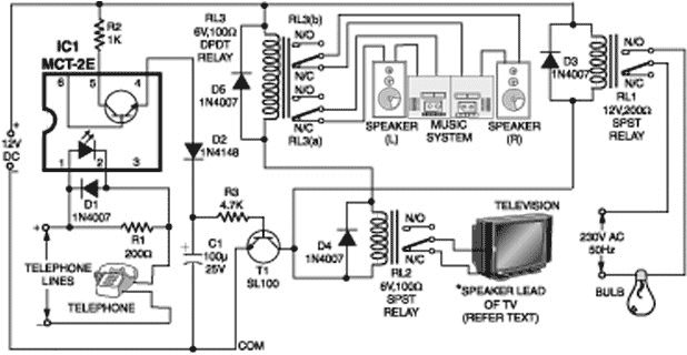
A telephone line-based audio muting and light activation circuit. Frequently, when listening to music or watching television at elevated volume levels, it becomes difficult to hear a telephone ring, resulting in missed important calls. This circuit is designed to address...
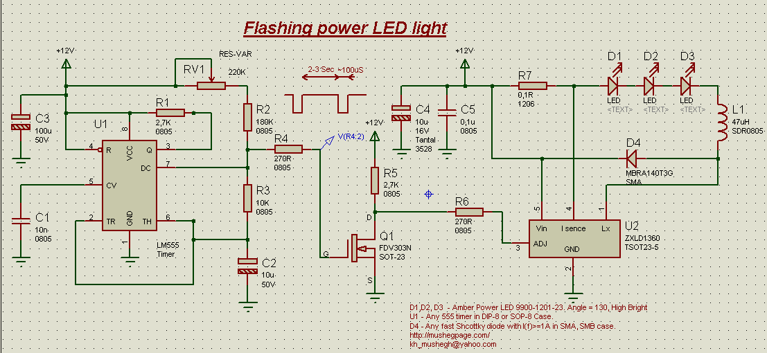
This project demonstrates the construction of a simple flashing light circuit using the IC 555 timer. The 555 timer functions as a clock generator with a duty cycle of less than 100% and greater than 50%. Additional components include...
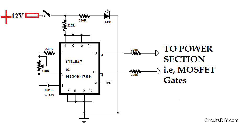
This simple and inexpensive yet powerful square wave oscillator can provide oscillation for any MOSFET-based inverter or UPS. The circuit features a central integrated circuit (IC), specifically the CD4047, with the HCF4047BE model from ST Microelectronics utilized. This design...
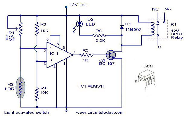
The following circuit illustrates a Light Activated Switch Circuit Diagram. This circuit is based on the LM311 integrated circuit, which functions as a voltage comparator. The Light Activated Switch Circuit utilizes the LM311 voltage comparator to control the switching of...