
Light Activated SwitchCircuit Based On The LM311 IC

The Light Activated Switch Circuit utilizes the LM311 voltage comparator to control the switching of a load based on ambient light levels. The circuit typically consists of a photodiode or phototransistor that detects light intensity. When the light level exceeds a predetermined threshold, the output of the LM311 changes state, activating a relay or transistor that controls the load.
In this configuration, the photodiode is connected to the inverting input of the LM311, while a reference voltage is applied to the non-inverting input. The reference voltage can be adjusted using a potentiometer, allowing for fine-tuning of the light sensitivity. When the light intensity surpasses the reference voltage, the LM311 output transitions from low to high, which can be used to drive a relay or transistor, thereby switching on the connected load.
The circuit may also include additional components such as resistors for current limiting and capacitors for noise filtering. Proper layout and component selection are crucial for ensuring the circuit's responsiveness to light changes and minimizing false triggering from ambient light fluctuations. This type of circuit is commonly employed in applications such as automatic street lighting, garden lights, and other systems that require light-sensitive control.The following circuit shows about Light Activated Switch Circuit Diagram. This circuit based on the LM311 IC Features: voltage comparator circuit .. 🔗 External reference
Related Circuits
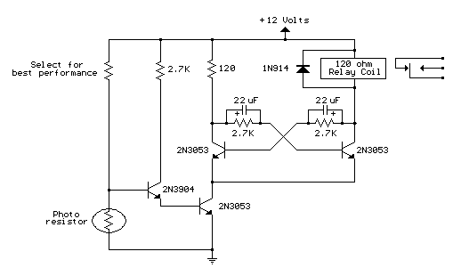
This circuit is similar to the previous one but incorporates a photoresistor to trigger the flip-flop instead of a push button. A bias resistor is placed in series with the photoresistor to ensure that adequate voltage is present at...

The SLB0586A integrated circuit from Siemens can be utilized to create a simple touch light dimmer circuit, allowing for the adjustment of lamp intensity. When paired with a TIC206D triac, this setup enables smooth regulation of light intensity for...

An infra-red or wireless remote control has the disadvantage that the small, handy, remote transmitter is often misplaced. The sound operated switch has the advantage that the transmitter is always with you. This project offers a way to control...
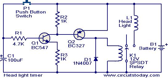
This circuit is a compact timer that keeps the headlights of a car on for approximately 1.5 minutes before turning them off. Incorporating this circuit into a vehicle allows access to dark areas without the need to return and...
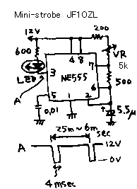
This is a mini strobe light. NE555 is used as a self-oscillator. The width of the output pulse is changed by the variable resistor. 25 msec means 40 Hz. 6 msec means 166 Hz. A LED is connected to...

A magnet is positioned on the door, while a magnetic reed switch is installed on the door casing. When the door is closed, the circuit is disabled. When the door is opened, the circuit becomes active. In this circuit design,...