
Three amplifier active filter
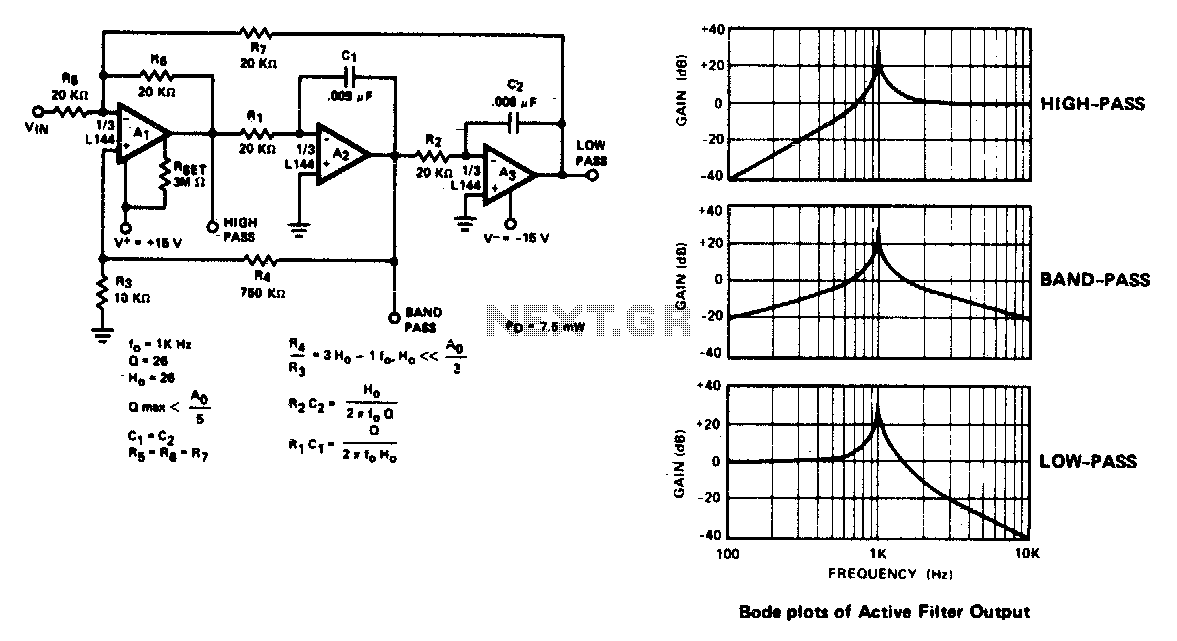
The state variable filter is a versatile circuit design that provides multiple output types, including bandpass, high-pass, and low-pass signals. This configuration is particularly useful in applications where different frequency components of a signal need to be isolated or processed separately. The core of this filter consists of three operational amplifiers (op-amps) and two capacitors, which work together to create a stable and tunable filtering system.
In this filter design, the first op-amp is configured as a high-pass filter. It allows high-frequency signals to pass while attenuating lower frequencies. The output of this stage is then fed into the second op-amp, which is configured as a low-pass filter. This stage allows low-frequency signals to pass while attenuating higher frequencies. The third op-amp combines the outputs of the first two to create a bandpass output, which selectively allows a specific range of frequencies to pass through while rejecting frequencies outside this range.
The use of only two capacitors in this design simplifies the circuit and reduces component count, making it cost-effective and easier to implement. The frequency response of each output can be adjusted by varying the values of the capacitors and resistors in the circuit, allowing for a high degree of flexibility in tuning the filter for specific applications.
This active filter design is widely utilized in audio processing, signal conditioning, and communication systems, where precise frequency selection is crucial for optimal performance. The state variable filter's ability to produce multiple outputs from a single configuration makes it a preferred choice in many electronic applications.The active filter is a state variable filter with bandpass, high-pass and low-pass outputs It is a classical analog computer method of implementing a filter using three amplifiers and only two capacitors. 🔗 External reference
Related Circuits

This filter circuit, which utilizes the LM1458 or a similar operational amplifier, has a frequency response ranging from 300 Hz to 3.4 kHz, exhibiting a roll-off of 12 dB per octave outside the passband. Section A serves as the...
Separates 130-cps motor drive voltage from voice frequencies in the output of an ADF receiver. P. V. Sparks, Servo Filter and Gain Control Improve Automatic Direction Finder, Electronics, 34:23, p 110-113. The circuit described functions as a filter that effectively...
This FM RF power amplifier circuit is constructed using a BLY94 transistor, which can deliver up to 50W at a frequency of 175MHz with a power gain of 7dB, resulting in approximately 5 times power amplification. However, in this...
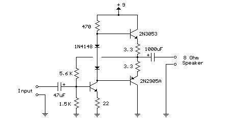
This weblog focuses on electronic circuit schematics, PCB design, DIY kits, and electronic project diagrams. The following describes a small audio amplifier, similar to those found in medium-sized transistor radios. The input stage is biased to ensure equal power...
The circuit utilizes two 2N3819 FETs arranged in a cascode configuration. The lower FET functions in common source mode, while the upper FET operates in common gate mode, achieving full high-frequency gain. The lower FET is adjustable, enabling tuning...
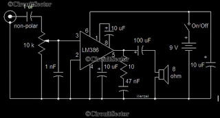
This is a simple low-power audio amplifier circuit capable of producing a power output of 1W. The mono amplifier circuit is built around the LM386 integrated circuit, which operates effectively at low voltages, even below 9V. This low-voltage amplifier...
Warning: include(partials/cookie-banner.php): Failed to open stream: Permission denied in /var/www/html/nextgr/view-circuit.php on line 713
Warning: include(): Failed opening 'partials/cookie-banner.php' for inclusion (include_path='.:/usr/share/php') in /var/www/html/nextgr/view-circuit.php on line 713