
Three astable circuit diagram
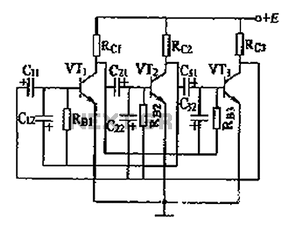
The astable multivibrator circuit consists of three transistors arranged in a cascading configuration, each serving as a switch that alternates between on and off states. The coupling capacitors between the transistor bases facilitate the timing and synchronization of the switching operation. When one transistor is driven into saturation, it allows current to flow through the collector-emitter junction, effectively turning on the next transistor in the sequence.
The biasing resistors (Rb) connected to the base of each transistor ensure that they operate within their active regions during the switching process. This arrangement prevents multiple transistors from being saturated simultaneously, thereby maintaining a stable oscillation pattern. The timing of the transitions is determined by the values of the resistors and capacitors used in the circuit.
In practical applications, this astable multivibrator can be utilized for generating square wave signals, timing applications, or as a clock pulse generator in digital circuits. The frequency of oscillation can be adjusted by modifying the capacitor values or the resistor values, allowing for versatile operation in various electronic systems. Overall, the design ensures reliable performance and efficient switching behavior, making it suitable for a wide range of electronic applications. As shown for the three astable circuit. From this circuit can be seen, each level of the base of the transistor by a capacitor connected between the two levels are tightly coup led by a capacitor and the collector to other levels, and at all levels of the base electrode bias resistor Rb and stage connected to the collector. This ensures that at the same time only one tube is saturated, while the other levels to the OFF state, a saturated tube front to the rear and then click Convert.
Related Circuits
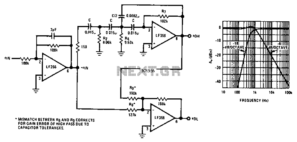
Asymmetric third-order Butterworth active crossover network circuit diagram. The asymmetric third-order Butterworth active crossover network is a sophisticated circuit designed to split an audio signal into two separate frequency bands, typically for use in multi-way speaker systems. This type of...
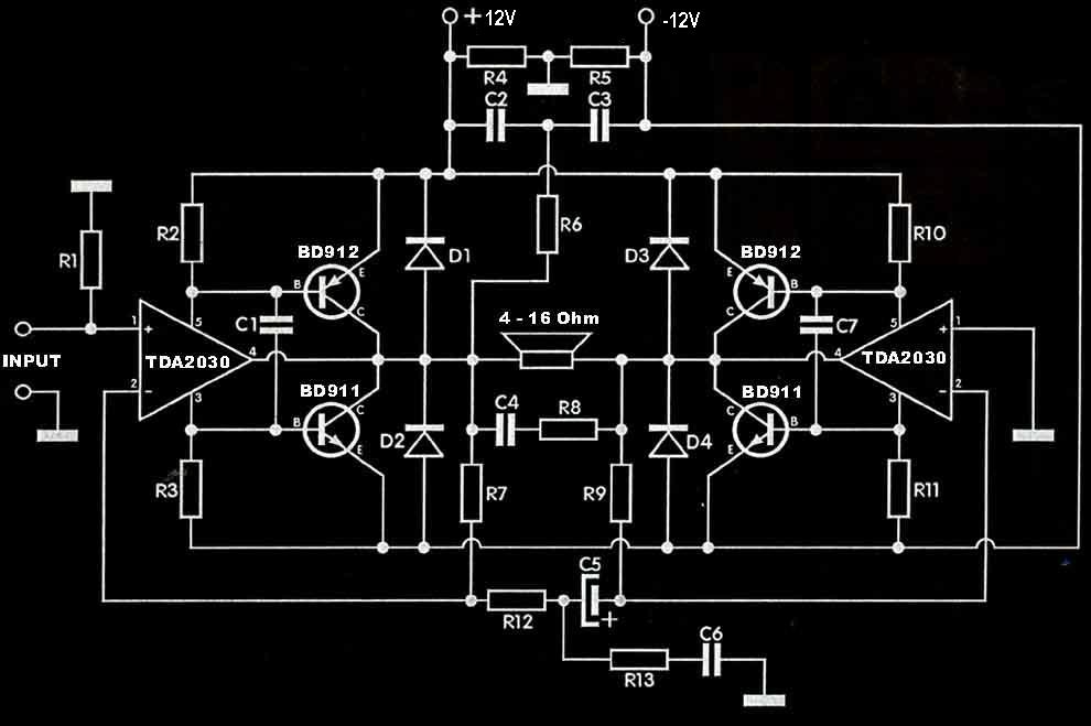
The TDA2030 amplifier circuit is suitable for driving low-frequency subwoofer speakers in home theater systems. The TDA2030 is a monolithic integrated circuit designed for use as a low-frequency class AB amplifier. This TDA2030 amplifier design requires a dual power...
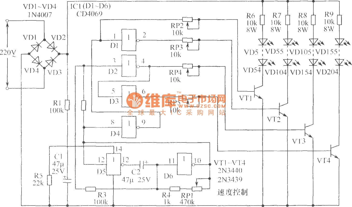
The chart illustrates a Christmas lights circuit that employs a simple and cost-effective CD4069 CMOS hex inverter to control four separate circuits, each consisting of 50 light-emitting diodes (LEDs), totaling 200 LEDs. The circuit is powered directly by a...
The impedance of these current generators is essentially infinite for small currents, and they maintain accuracy as long as VIN is significantly greater than VOS and IO is much higher than I bias. The source employs a FET to...
A simple preamplifier circuit is often required, utilizing a few components for ease of construction. This circuit employs an operational amplifier, specifically the Motorola TCA5550, which features a dual amplifier configuration. It provides outputs for adjusting volume, balance, treble,...
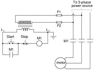
The most challenging aspect of interpreting ladder diagrams, particularly for individuals familiar with electronic schematic diagrams, is the representation of electromechanical relays. The operation of a motor control circuit should be explained, detailing what occurs when the "Run" switch...