
THREE INPUT TWO PENTODE MIXER

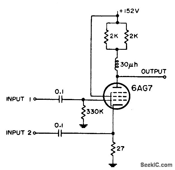
In this circuit design, the integration of distance markers and intermediate frequency (IF) signals is accomplished by utilizing a dual-grid tube configuration. The first tube is configured to accept both distance markers and IF signals at distinct grids, ensuring that these two types of signals do not interfere with each other. This separation is crucial for maintaining signal integrity and clarity during processing.
The second tube in the circuit is a pentode, which is particularly effective in amplifying weak signals due to its additional control grid. In this configuration, the radar video signal sourced from input 3 is applied to the control grid of the pentode. This allows for effective modulation and amplification of the radar video, which is essential for radar signal processing applications.
The use of a pentode in this context is significant, as it provides enhanced performance characteristics such as high gain and low noise, which are critical in radar systems. The design ensures that the radar video signal can be processed efficiently without degradation, enabling accurate distance measurement and signal interpretation.
Overall, this circuit exemplifies a sophisticated approach to radar signal processing, leveraging the unique properties of electron tubes to achieve reliable performance in aeronautical electronic equipment. The careful arrangement of signals and the choice of components reflect a deep understanding of electronic circuit design principles, particularly in the context of radar technology.Distance markers and iff signals are inserted at separate grids on one tube, while radar video from input 3 is impressed on control grid of other pentode. -NBS, "Handbook Preferred Circuits Navy Aeronautical Electronic Equipment, " Vol. l, Electron Tube Circuits, 1963, p N4-4. 🔗 External reference
Related Circuits

CMOS switches are utilized to select entries in audio circuits. While these switches can introduce unacceptable levels of distortion, incorporating them into the feedback network of an operational amplifier (op amp) can effectively minimize this distortion. The circuit employs...
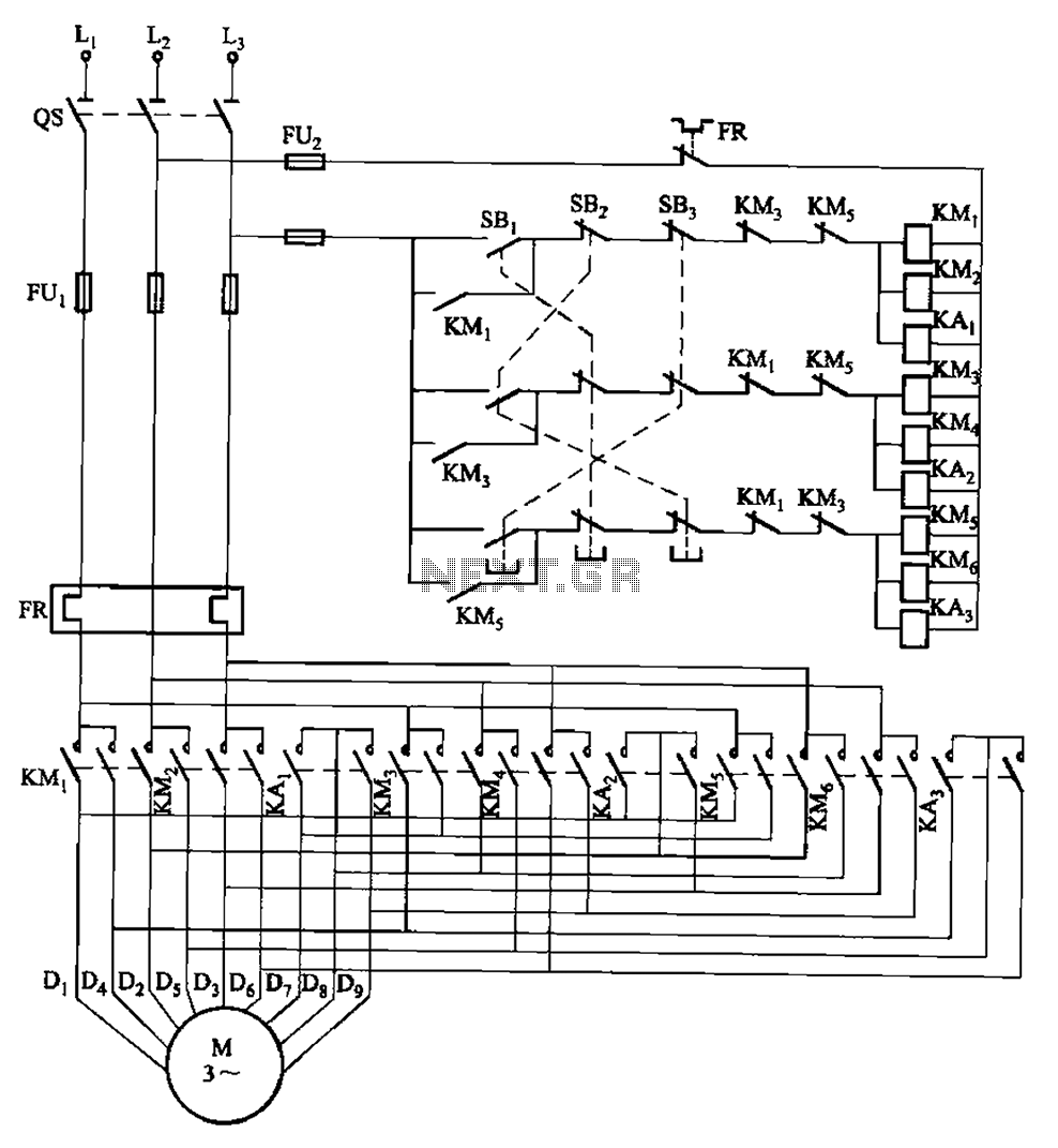
The circuit depicted in Figure 3-115 utilizes contactors and double buttons, allowing for speed conversion without the need to press the stop button. The buttons SBi, SBz, and SB3 correspond to high, medium, and low-speed operation, respectively. This circuit design...

The KCZ3 is an integrated three-pulse triggering component designed for use in three-phase half-bridge inverters. Each phase output pulse can reliably drive a high-power thyristor and is adaptable to various phase voltages. The electrical parameters are as follows: Phase...

A relay is controlled by a closed circuit in a digital logic setup, utilizing a touch input switching circuit. The described circuit involves a relay that operates based on a closed circuit condition within a digital logic framework. The relay...
Negative video and intermediate frequency (IFF) signals are introduced at the grid, while a range strobe signal from the cathode output of a blocking oscillator is applied to the cathode. -NBS, "Handbook Preferred Circuits Navy Aeronautical Electronic Equipment," Vol....
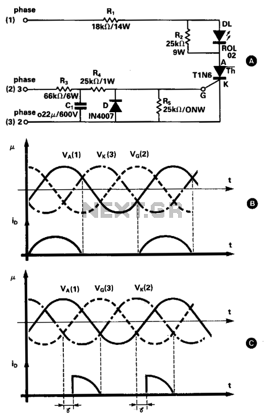
This simple three-phase tester utilizes a small current thyristor as the main component for verifying the correct or incorrect sequence of the three phases, eliminating the need for an additional power supply. The basic circuit is depicted in Fig....
Warning: include(partials/cookie-banner.php): Failed to open stream: Permission denied in /var/www/html/nextgr/view-circuit.php on line 713
Warning: include(): Failed opening 'partials/cookie-banner.php' for inclusion (include_path='.:/usr/share/php') in /var/www/html/nextgr/view-circuit.php on line 713