
Audio input selector circuit (4416 CMOS)
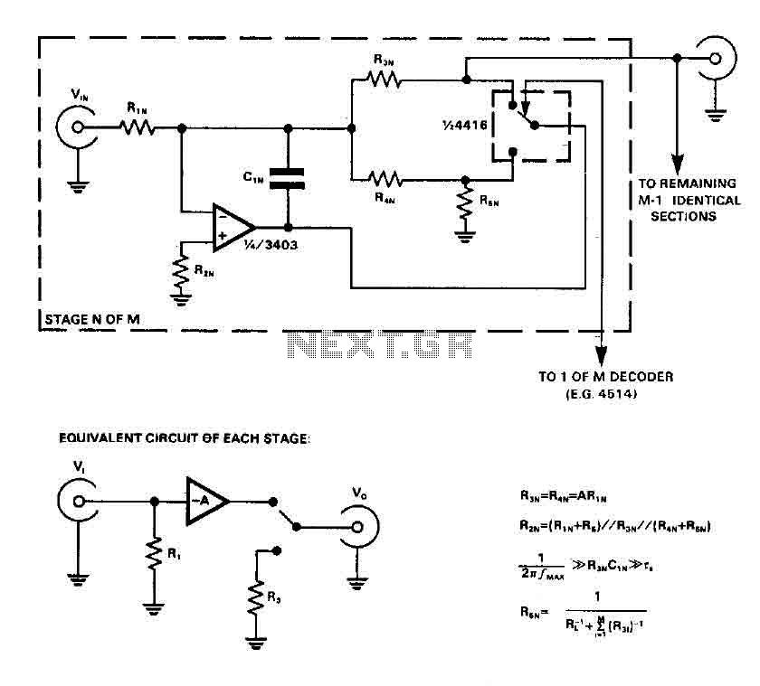
In audio circuit design, CMOS switches, such as the 4416 model, are integrated to facilitate the selection of different audio sources or signals with minimal distortion. The operational amplifier's feedback network plays a crucial role in maintaining signal integrity. By placing the CMOS switch within this feedback loop, the circuit can effectively counteract the distortion typically introduced by the switch itself.
The configuration as two independent SPDT switches allows for versatile routing of audio signals, enabling the selection of one of several inputs while maintaining a consistent output. This design choice enhances the flexibility of the circuit while ensuring that the audio quality remains high.
When considering the components of the circuit, R5 and C1 serve as a low-pass filter that can mitigate switching transients. However, in applications where these transients do not impact performance, these components can be removed to simplify the design. R4, which may be short-circuited, is often used to set a specific bias point or to stabilize the circuit under certain conditions.
Maintaining a return path is critical to ensure that when one channel is switched off, the inverting input of the op amp remains at ground potential. This is vital in preventing crosstalk, which can lead to undesired interference between channels, thereby preserving the clarity and fidelity of the audio signals. The overall design of the circuit, with careful consideration of component placement and configuration, is essential for achieving optimal performance in audio applications.CMOS switches are used directly to select the entries in the audio circuits, it can introduce unacceptable levels of distortion, but if the switch is included in the feedback network of an op amp, the distortion due to the switch may be virtually eliminated. The circuit uses a CMOS switch 4416, arranged as two independent SPDT switches. If switching transients are unimportant, R5 and C1 can be omitted, and R4 may be short-circuited. However, a return path must be maintained even if a channel is turned off, to keep the inverting input of op amp to ground potential, and avoid excessive crosstalk between channels. 🔗 External reference
Related Circuits
The audio ground is completely isolated from the digital ground. The top copper layer is utilized as a shield for both the audio and digital ground, which aids in preventing the audio section from picking up noise from the...
Various values of D3 can be utilized to achieve different output voltages ranging from approximately 0.6V to around 30V. It is important to note that at elevated voltages, the circuit's performance may diminish, potentially resulting in lower current output....
This circuit generates a two-tone effect similar to the cuckoo song. It can be utilized for doorbells or other applications due to its integrated audio amplifier and loudspeaker. As a sound effect generator, it can connect to external amplifiers,...
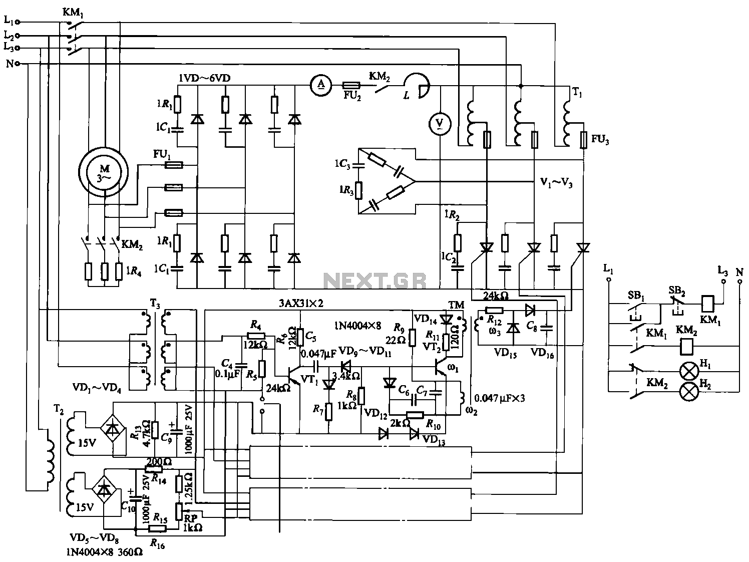
The circuit depicted in Figure 3-170 illustrates a wound rotor induction motor operating at various speeds, with a voltage (turn difference frequency EMF) U induced in the rotor. The rotor open circuit voltage is represented as Uo (Us0). A...
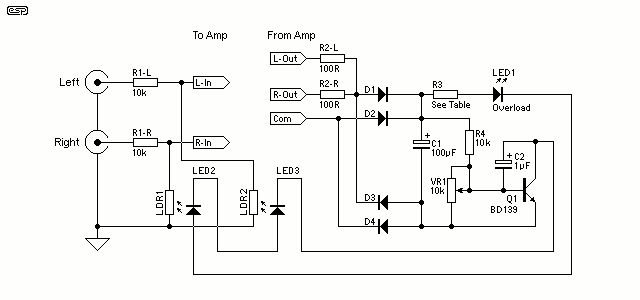
The gain control element is a Light Dependent Resistor (LDR). These are blessed with a few very useful features for our purposes, one of which is low distortion even at quite high signal levels. Being light activated, all we...
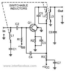
This page presents several transistor circuits that are not commonly found on other pages due to the absence of a specific topic. These circuits, however, illustrate particular points but lack detailed descriptions. An example of an RF amplifier circuit...