
Three phase tester
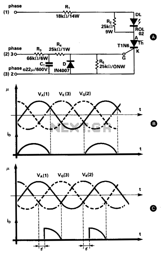
This three-phase tester circuit is designed to verify the correct sequence of phase connections in a three-phase power system. The thyristor serves as a critical element that responds to the phase sequence, allowing for a simple visual indication through the LED.
The circuit operates by connecting the three phases to the thyristor's anode, gate, and cathode. When the phases are connected in the correct order (phase 1 to anode, phase 3 to gate, and phase 2 to cathode), the thyristor remains in the conducting state for a significant portion of the AC cycle, which ensures a stable flow of current through the LED. This results in a normal brightness of the LED, indicating that the phase sequence is correct. The accompanying voltage waveforms, as illustrated in Fig. 69-4B, demonstrate the expected behavior of the circuit under these conditions.
Conversely, if the phases are misconfigured, the thyristor will only conduct for a very short period. This reduced conduction time leads to a significantly lower average current through the LED, causing it to emit a dim light. The waveforms for this incorrect connection scenario, as shown in Fig. 69-4C, highlight the difference in operation when the phase sequence is not adhered to.
The timing characteristics of the circuit are influenced by the resistor network formed by R3, R1, and R4, which establishes the delay time for the thyristor's response. Additionally, if any of the three phases is missing from the circuit, the thyristor will not receive the necessary current to operate, resulting in the LED remaining off.
Overall, this three-phase tester provides a straightforward and effective method for ensuring proper phase sequence in three-phase systems, making it an invaluable tool for electrical engineers and technicians working with such installations.This simple three-phase tester, uses only a small current thyristor as a main element for testing the right or wrong succession of the three phases, and there is no need for a supplementary power supply. The basic circuit is shown in Fig. 69-4A. When connecting to the thyristor anode, grid, and cathode the three phases of the supply network in the sequence phase 1, phase 3, phase 2, are considered as correct, the mean value of the current through the thyristor is relatively high (since it is turned on during an entire half-period of one phase).
The result is that the LED will emit a normal light. The wave shapes for the three voltages and the current through the LED for this situation are shown in Fig. 69-4B. If the three phases are not correctly connected—phase 1 to the anode, phase 2 to the grid, and phase 3 to the cathode, for instance—the thyristor will be turned on for a very short time and the LED wili produce a very poor light. The wave shapes for this case are shown in Fig. 69-4C. The delay time is given by the R3-R1-R4 group. When any of the three phases is missing, there is no current through the thyristor and the LED will emit no light.
🔗 External reference
Related Circuits
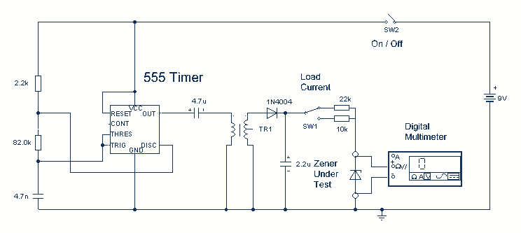
Using a single 555 Timer IC and a small transformer to generate a high voltage, this circuit will test zener diodes of voltage ratings up to 50VDC. The 555 timer is used in the astable mode, the output at...
The continuity tester is designed for tracing wiring on printed circuit boards. It consumes significant power only when the test leads are shorted, eliminating the need for an On/Off switch. The voltage applied at the test terminals is not...
Camping today often requires bringing various electronic devices for daily use or entertainment. Typically, a charged lead-acid battery and a power inverter are utilized to ensure a well-organized holiday where family members can enjoy their electronic gadgets. It is...
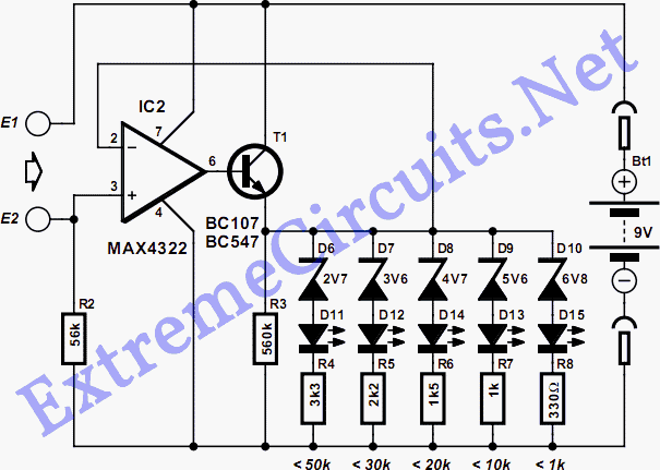
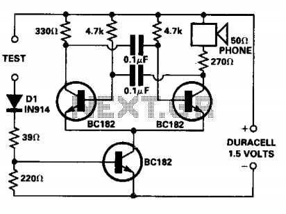
The continuity tester is a useful accessory to an ohmmeter. The unit or component whose continuity is to be checked is connected between terminals E1 and E2. A continuity tester is an essential tool in electronics for verifying the integrity...
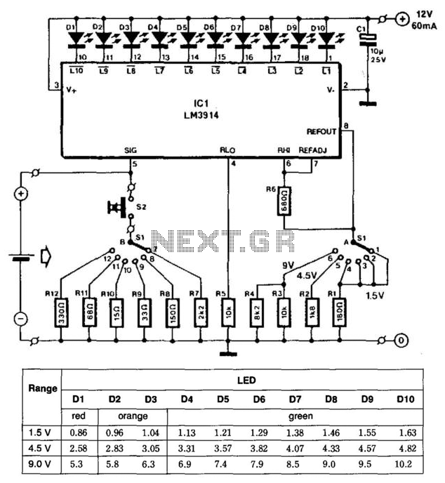
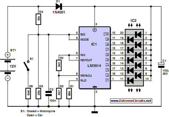
This battery tester utilizes an LM3914 bar-graph driver integrated circuit (IC). Switch SI selects the load on the battery being tested and programs the voltage range. Switch S2 applies the load to the battery under test. A table provides...
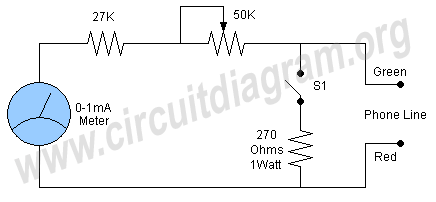
A simple and easy telephone line tester circuit that can be used for testing telephone lines. The telephone line tester circuit is designed to verify the functionality and integrity of telephone lines. It typically comprises a few essential components, including...