
Three lighting sound and light control switch circuits
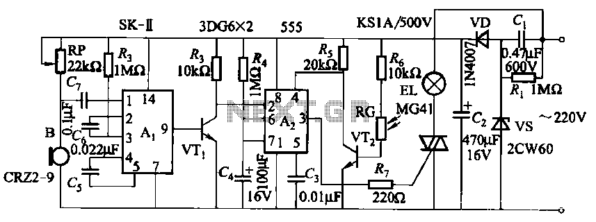
The described circuit is designed to process and reproduce voice signals using a dedicated voice IC, specifically the SK type. This integrated circuit is engineered to handle voice synthesis and playback, making it suitable for applications such as greeting cards, toys, or automated messaging systems.
The internal structure of the SK voice IC includes a bistable multivibrator, which allows the circuit to maintain one of two stable states. This feature is crucial for triggering the playback of voice messages based on external inputs, such as a push button or a motion sensor. The three inverting amplifiers serve to amplify the voice signal, ensuring that the output is loud enough for clear playback. This amplification is essential in applications where the voice needs to be heard over background noise or in larger spaces.
The 555 timer IC, designated as A2 in this circuit, is configured to provide a delay control function. This allows the circuit to introduce a time delay before the voice playback begins, which can be useful in various applications where a pause is desired before the message is triggered. The 555 timer can be configured in monostable mode, where it produces a single output pulse of a specified duration in response to an external trigger, or in astable mode for continuous operation.
In summary, this circuit combines a dedicated voice IC with a bistable multivibrator and amplifiers, along with a 555 timer for delay control, to create an effective voice playback system. The design allows for versatility in triggering and amplifying voice messages, making it suitable for a range of electronic applications.This circuit uses a dedicated voice integrated circuits Ai (SK- type), its internal features bistable multivibrator and three inverting amplifier. 555 IC A2 for the delay control.
Related Circuits

Design a low-cost 4- to 20-mA receiver circuit for control loops using an analog-to-digital converter (ADC). The design of a low-cost 4- to 20-mA receiver circuit is essential in industrial applications for monitoring and controlling processes. This current loop standard...
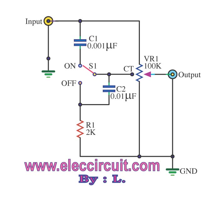
The passive tone control circuit is designed to adjust the bass without expansion, utilizing resistors (R) and capacitors (C). It functions as a frequency filter and is easy to construct, requiring no external power supply. This circuit can be...
Sound effects generators trying to imitate rain sound or sea surf are well known to hobbyists from many years: their purpose is to induce relaxation and sleep or to help in concentration and study. The sound generated is restrained...
To provide rapid motor speed changes and motor direction reversal, four outputs drive a MOSFET H-bridge. N-channel devices serve as the lower rail power MOSFETs, while P-channel devices are utilized as the upper MOSFETs. All MOSFETs are controlled by...
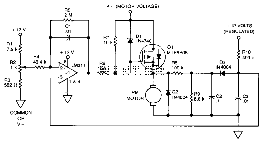
The use of power MOSFETs facilitates a direct interface between logic and motor power, enabling circuit simplicity and high efficiency. This speed control circuit can be implemented on a 22-pin, double-sided, 3.5 x 4-inch printed circuit board (PCB). A...
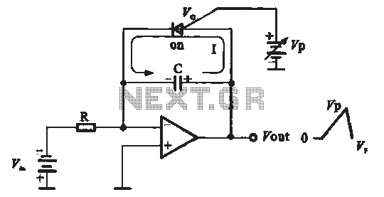
A sawtooth voltage-controlled oscillator operates by first generating a negative potential maximum at the output of the comparator. This output is then fed to the inverting input terminal through resistor R1, which is part of the relaxation oscillator. The...
Warning: include(partials/cookie-banner.php): Failed to open stream: Permission denied in /var/www/html/nextgr/view-circuit.php on line 713
Warning: include(): Failed opening 'partials/cookie-banner.php' for inclusion (include_path='.:/usr/share/php') in /var/www/html/nextgr/view-circuit.php on line 713