
555 IC PWM Motor Control with Current Limiter
The described circuit employs a MOSFET H-bridge configuration to enable rapid adjustments in motor speed and direction. The H-bridge consists of four MOSFETs, specifically N-channel types for the lower rail and P-channel types for the upper rail. The TC4469 driver is responsible for controlling the gate signals of these MOSFETs, ensuring efficient switching and performance.
To enhance the reliability of the gate control, a small series resistor is incorporated into the design. This resistor serves two primary purposes: it dampens potential oscillations at the gate and slows down the transition times for the lower rail MOSFETs, which is critical for ensuring that the upper rail MOSFETs remain OFF during switching events. This design consideration reduces the risk of unintended turn-on of the upper MOSFETs, thereby improving the overall stability of the H-bridge operation.
In applications where the motor voltage exceeds 12VDC, maintaining a consistent gate voltage of 15VDC for the upper rail MOSFETs is crucial. A resistor divider and a low-cost level-shifting transistor can be integrated into the circuit to achieve this requirement economically. When the motor supply voltage is above 15VDC, a linear regulator can be employed to derive the necessary gate drive voltage for the upper MOSFETs, ensuring that the TC4469 and ICM7555 operate efficiently without drawing significant current.
Protection against supply transients is another essential aspect of the design. The inclusion of Zener diodes serves as a safeguard for the gate terminals, mitigating the risk of damage from voltage spikes. Furthermore, the use of gate-to-source capacitors plays a vital role in maintaining the upper MOSFETs in the OFF state when the lower MOSFETs are activated, especially during high dV/dT conditions.
Current sensing is facilitated through the use of a sense resistor located in the ground leg of the H-bridge. This configuration allows for accurate monitoring of the motor current on a pulse-by-pulse basis, regardless of the direction of rotation. The sensed current signal is filtered and fed into the ICM7555, which can inhibit PWM generation if the current exceeds predefined limits, thus protecting the motor and driver circuit from potential damage due to overcurrent conditions.
This comprehensive approach ensures robust control of motor operations, combining efficient drive techniques, protective measures, and effective current sensing to enhance the performance and reliability of the motor control system.To provide rapid motor speed changes and motor direction reversal, four outputs drive a MOSFET H-bridge. N-channel devices are the lower rail power MOSFETs and P-channels are the upper MOSFETs. All of them are driven by the TC4469. A small series resistor helps prevent gate oscillation and slows transition time in the lower rail devices, helping t
he upper device to stay OFF. A resistor divider and low-cost level shift transistor can be added easily and economically to maintain a 15VDC gate drive for the upper rail MOSFETs for motor voltages over 12VDC. A simple linear regulator can power them from the positive motor supply when it is above 15VDC since the ICM7555 and TC4469 need negligible current.
To help protect the gates from supply transients, we can use a Zener diodes. When the lower MOSFET in the same leg turns ON , causing a high dV/dT, gate-to-source capacitors help keep the upper MOSFETs OFF . The other way to help that situation is keeping the upper MOSFET gate drive impedance low in the OFF state.
An easy way to sense motor current, pulse by pulse, regardless of forward or reverse motor rotation is provided by a sense resistor in the ground leg of the H-bridge. To inhibit PWM generation if motor current exceeds the allowed value, this signal is filtered and applied to the ICM7555.
[Microchip Application Notes] We aim to transmit more information by carrying articles. Please send us an E-mail to wanghuali@hqew. net within 15 days if we are involved in the problems of article content, copyright or other problems. We will delete it soon. 🔗 External reference
Related Circuits
The LM1036 is a DC-controlled circuit designed for adjusting tone (bass/treble), volume, and balance in stereo applications such as car radios, televisions, and audio systems. It features an additional control input that enables straightforward loudness compensation. Four control inputs...
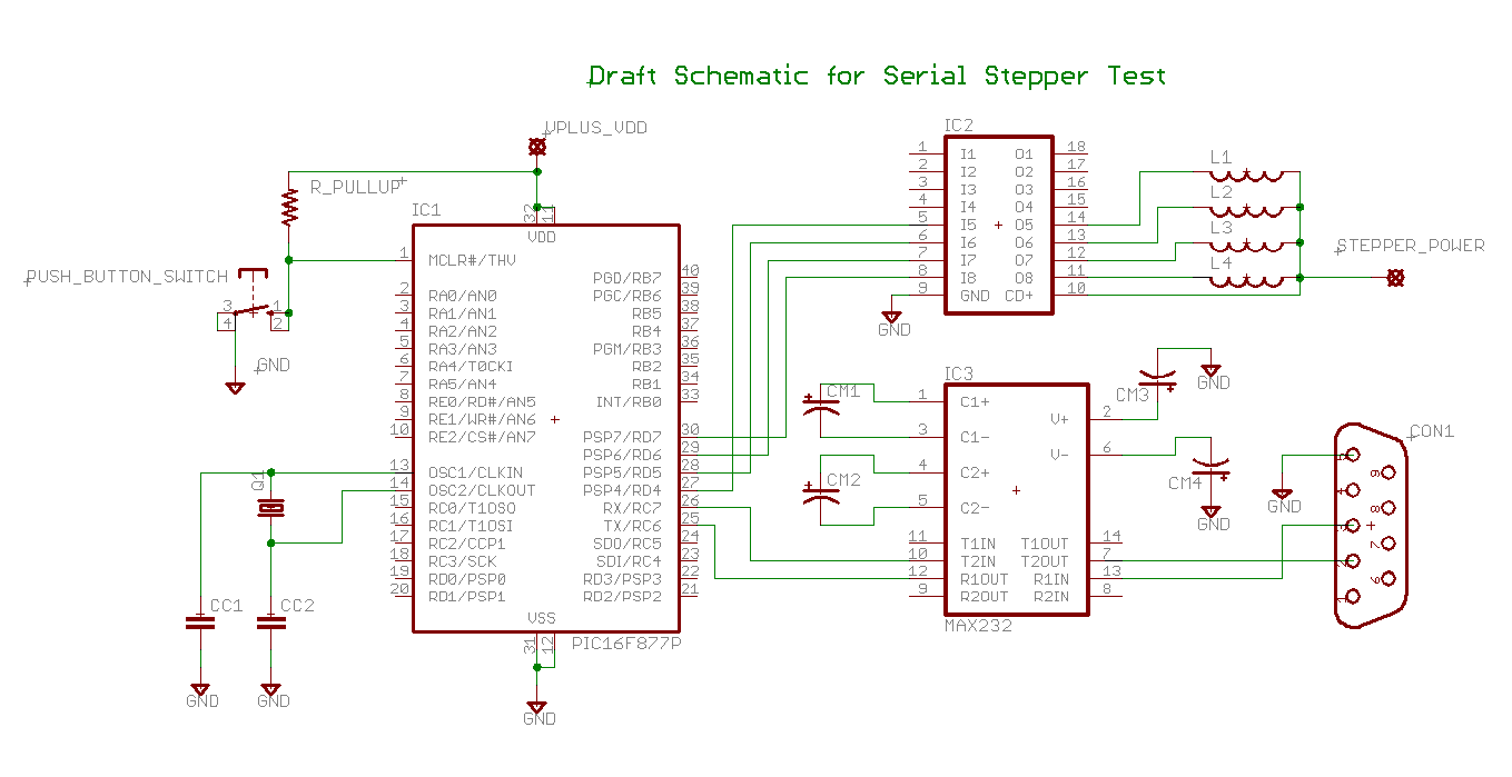
Determining the identification of drive wires on a unipolar stepper motor, which is commonly found in surplus or salvaged equipment. The platform utilized is a PIC16F877A microcontroller programmed with BoostC, interfaced via RS232 to a PC running a terminal...
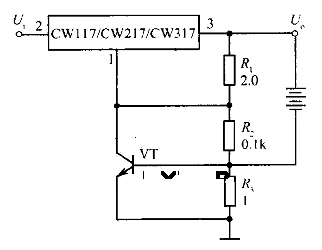
The circuit depicted in the figure is a limiting protection charger. The VT transistors and resistor R3 create a limiting network. As illustrated, resistor R3 is connected in series with the battery being charged, acting as the emitter resistor...
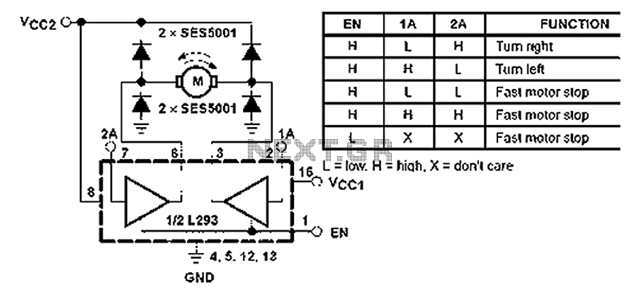
All inputs are compatible with TTL. Each output consists of a complete totem pole driver circuit, utilizing Darlington transistors and pseudo-Darlington sources. The driver enable signals, labeled as 1,2 EN and 3,4 EN, control the activation of drivers 1...
I have had this project hanging around for ages and have tried to submit it for publication without much enthusiasm so I will make everything available here for the individual constructor. The complete Pascal source code for the compiler...
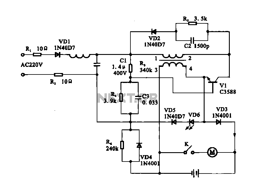
Electric shaver motor drive circuit. It illustrates a typical motor drive circuit for an electric shaver. AC 220V is used to charge the battery through the charging circuit, which also provides power to the motor. After activating the charge-on...