
Back emf motor speed control

The circuit design leverages the advantages of power MOSFETs, allowing for efficient control of the motor's speed and direction. The incorporation of a 22-pin double-sided PCB enhances the circuit's compactness and facilitates efficient layout and routing. The choice of a 12 V control supply alongside a 30 V motor provides flexibility, allowing the circuit to be adapted for various applications with minimal alterations.
The speed control mechanism is centered around potentiometer R2, which functions as a variable resistor, enabling the user to adjust the voltage supplied to the positive input of comparator U1. Comparator U1 compares this voltage with the feedback voltage derived from the motor's back EMF. The feedback network, comprising resistors R8, R9, R10, capacitors C2 and C3, and diode D3, ensures that the motor speed remains stable and responsive to adjustments made via R2.
The output of comparator U1 drives the MOSFET Q1 (MTP8P08), which acts as a switch to control the power supplied to the motor. The Zener diode D1 plays a critical role in protecting the gate of the MOSFET from voltage spikes, ensuring reliable operation. The design allows for precise control over the motor's operation, including starting, stopping, reversing, and oscillating, with the added feature of a variable delay that can be adjusted to suit specific operational requirements.
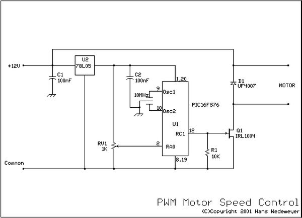
Overall, the design emphasizes high efficiency and simplicity, making it suitable for various applications in motor control systems where precise speed regulation and reliability are paramount.The use of power MOSFETs allows a direct interface between logic and motor power, which permits circuit simplicity as well as high efficiency. This speed control circuit can be packaged on a 22-pin, double-sided, 3.5 4-in. pc board. A 12 V control supply and a TRW BL11, 30 V motor are used; with minor changes other motor and control voltages can be accommodated.
For example, a single 24 V rail could supply both control and motor voltages. Motor and control voltages are kept separate here because CMOS logic is used to start, stop, reverse and oscillate the motor with a variable delay between motor reversals. Motor speed is established by potentiometer R2, which applies a corresponding dc voltage to the + input of comparator Ul, whose output is then applied to TMOS device MTP8P08 (Ql). Zener diode Dl limits the drive to Ql. The output of Ql drives the permanent magnet motor.Back emf is obtained from the motor via the network consisting of R8, R9, RIO, C2, C3 and D3; it is applied to—input of comparator Ul.
Related Circuits
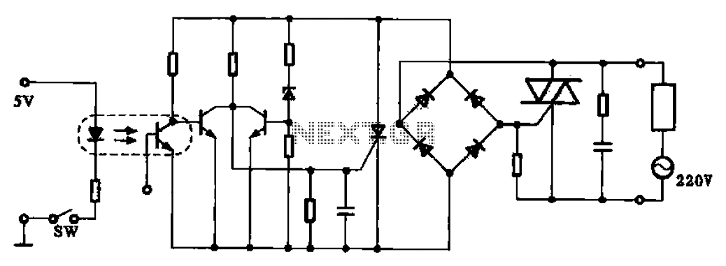
This application example illustrates a photovoltaic control circuit. In this circuit, the Triac functions as a solid-state relay, providing an AC power supply path to the load. It is designed to achieve high current control signals using a small...
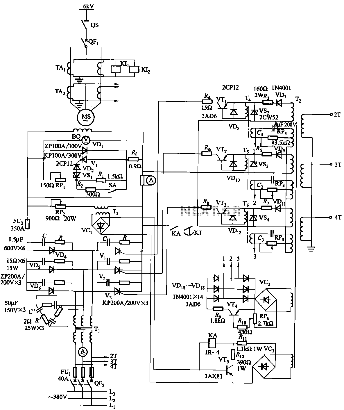
The excitation device for a light-duty synchronous motor rated at 625 kW has been initiated. The triggering circuit of the device consists of three identical RC phase-shift flip-flops. Adjustment potentiometers RP3 to RPs are used to set the RC...

A simple linear voltage-controlled amplifier can be constructed with one operational amplifier (op amp) and two junction field-effect transistors (JFETs). This amplifier can achieve an 80-dB dynamic control range with less than ±0.2% linearity error for 0 V. The described...
If EAGLE is not available, a full working version can be downloaded from CadSoftUSA. A zip file containing the EAGLE schematics is provided. The EAGLE software is a widely used electronic design automation (EDA) tool that facilitates the creation of...
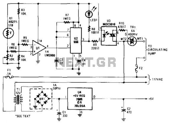
A thermistor (R1) is compared with a reference resistor (R2) in a Wheatstone bridge circuit. The output of comparator U1 goes high, which triggers U2. U2 introduces a delay of approximately 25 seconds. After 15 seconds, LED1 illuminates, U3...
A simple single-transistor circuit provides an approximate 15 dB boost at 100 Hz and a 15 dB cut at 15 kHz. A low-noise audio transistor is utilized, and the output can be directly connected to any existing amplifier volume...