
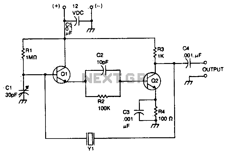
Phase-shift oscillator
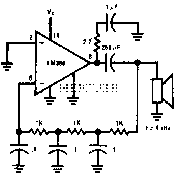
The circuit is designed around a simple resistor-capacitor (RC) network that forms the basis of an oscillator. The RC values are carefully selected to achieve the desired frequency of oscillation, which is critical for producing the high-pitched tone. The oscillator output is a square wave, characterized by its rapid transitions between high and low states, which is suitable for driving a miniature speaker.
The miniature speaker, rated at 2 watts, is capable of producing loud sounds, making it ideal for applications requiring attention-grabbing audio signals. The peak-to-peak voltage of 4 volts is sufficient to drive the speaker to high volumes, ensuring that the sound produced is piercing and easily audible.
Power considerations are also important in the design of this circuit. The oscillator operates at a current drain of 90 mA when supplied with 9 volts. This results in a total power dissipation of 0.1 watt, which is well within safe operating limits. The 14-pin version of the oscillator can tolerate up to 15 watts before it risks overheating and shutting down, thus providing a robust safety margin for extended use.
In summary, this circuit is an effective solution for generating a loud, shrill tone using a minimal component count, making it suitable for various applications, including alarms and notification systems. The design ensures efficient power usage while maintaining the ability to produce high sound levels, demonstrating the effectiveness of RC oscillators in audio applications.Circuit uses a simple RC network to produce an exceptionally shrill tone from a miniature speaker. With the parts values shown, the circuit oscillates at a frequency of 3 kHz and drives a miniature 2W speaker with ear-piercing volume. The output waveform is a square wave with a width of 150 µ$, sloping rise and fall times, and a peak-to-peak amplitude of 4 volts (when powered by 9 volts)
Current drain of the oscillator is 90 mA at 9 volts, and total power dissipation at this voltage is 01 watt, which is well below the 15 watts the 14-pin version will absorb (at room temperature) before shutting down. 🔗 External reference
Related Circuits
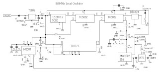
This 860 MHz Phase Locked Loop (PLL) oscillator circuit is designed for a 1200 MHz transverter's local oscillator with 435 MHz rigs. The oscillator utilizes Toshiba PLL synthesizer integrated circuits (ICs). The TC9122P serves as a preset counter for...
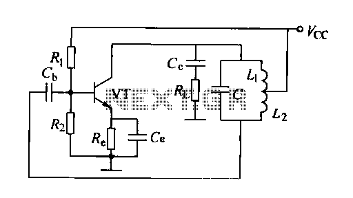
A feedback oscillator circuit utilizing inductance is presented, featuring the 3DG3 transistor. The component parameters reference values include: 1) transistors 3DG6, 2) resistances R1 at 91 kΩ, R2 at 11 kΩ, and R3 unspecified, 3) capacitance values of C...
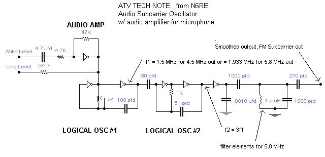
A single integrated circuit (IC) provides all amplifiers: the 74HC04 Hex Inverter, which is a digital component. The second oscillator synchronizes to three times the frequency of the first oscillator, thereby tripling the frequency modulation (FM) deviation. Utilizing the...
On following pages circuits are shown for 3rd overtone crystals 15 to 65MHz and 5th overtone crystals 60 to 105 MHz operating in their series resonant mode. In both of these circuits with the crystal short circuited, the oscillator...
This is a schematic diagram of a micropower voltage-controlled oscillator circuit. This circuit can generate square and triangle wave outputs and only requires minimal power. The micropower voltage-controlled oscillator (VCO) circuit is designed to produce both square and triangle waveforms,...
The crystal is positioned between the collector of the output stage and the base of the input stage. The oscillation frequency can be accurately adjusted using the trimmer capacitor CI. This circuit operates within a frequency range of 500...
Warning: include(partials/cookie-banner.php): Failed to open stream: Permission denied in /var/www/html/nextgr/view-circuit.php on line 713
Warning: include(): Failed opening 'partials/cookie-banner.php' for inclusion (include_path='.:/usr/share/php') in /var/www/html/nextgr/view-circuit.php on line 713